

VS1033 - MP3/AAC/WMA/MIDI AUDIO CODEC - VLSI Solution
VS1033 - MP3/AAC/WMA/MIDI AUDIO CODEC - VLSI Solution
VS1033 - MP3/AAC/WMA/MIDI AUDIO CODEC - VLSI Solution

Create successful ePaper yourself
Turn your PDF publications into a flip-book with our unique Google optimized e-Paper software.
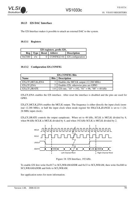
<strong>VLSI</strong><strong>Solution</strong> y<strong>VS1033</strong>c<strong>VS1033</strong>C10. <strong>VS1033</strong> REGISTERS10.13 I2S DAC InterfaceThe I2S Interface makes it possible to attach an external DAC to the system.10.13.1 RegistersI2S registers, prefix I2SReg Type Reset Abbrev Description0xC040 r/w 0 CONFIG[3:0] I2S configuration10.13.2 Configuration I2S CONFIGI2S CONFIG BitsName Bits DescriptionI2S CF MCLK ENA 3 Enables the MCLK output (12.288 MHz)I2S CF ENA 2 Enables I2S, otherwise pins are GPIOI2S CF SRATE 1:0 I2S rate, ”10” = 192, ”01” = 96, ”00” = 48 kHzI2S CF ENA enables the I2S interface. After reset the interface is disabled and the pins are used forGPIO.I2S CF MCLK ENA enables the MCLK output. The frequency is either directly the input clock (nominal12.288 MHz), or half the input clock when mode register bit SM CLK RANGE is set to 1 (24-26 MHz input clock).I2S CF SRATE controls the output samplerate. When set to 48 kHz, SCLK is MCLK divided by 8,when 96 kHz SCLK is MCLK divided by 4, and when 192 kHz SCLK is MCLK divided by 2.MCLKSCLKLROUTSDATAMSB LSB MSBLeft Channel WordRight Channel WordFigure 18: I2S Interface, 192 kHz.To enable I2S first write 0xc017 to SCI WRAMADDR and 0x33 to SCI WRAM, then write 0xc040 toSCI WRAMADDR and 0x0c to SCI WRAM.See application notes for more information.Version 1.00, 2008-02-01 70


