

3-Phase BLDC Motor Sensorless Control Using MC56F8013
3-Phase BLDC Motor Sensorless Control Using MC56F8013
3-Phase BLDC Motor Sensorless Control Using MC56F8013
- No tags were found...

You also want an ePaper? Increase the reach of your titles
YUMPU automatically turns print PDFs into web optimized ePapers that Google loves.
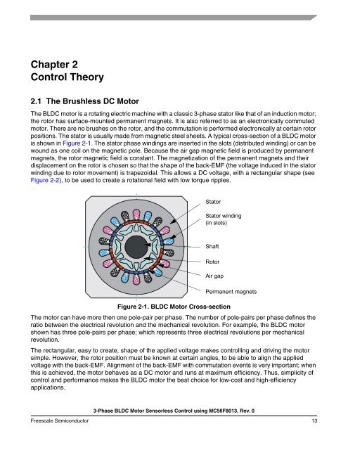
Chapter 2<strong>Control</strong> Theory2.1 The Brushless DC <strong>Motor</strong>The <strong>BLDC</strong> motor is a rotating electric machine with a classic 3-phase stator like that of an induction motor;the rotor has surface-mounted permanent magnets. It is also referred to as an electronically commutedmotor. There are no brushes on the rotor, and the commutation is performed electronically at certain rotorpositions. The stator is usually made from magnetic steel sheets. A typical cross-section of a <strong>BLDC</strong> motoris shown in Figure 2-1. The stator phase windings are inserted in the slots (distributed winding) or can bewound as one coil on the magnetic pole. Because the air gap magnetic field is produced by permanentmagnets, the rotor magnetic field is constant. The magnetization of the permanent magnets and theirdisplacement on the rotor is chosen so that the shape of the back-EMF (the voltage induced in the statorwinding due to rotor movement) is trapezoidal. This allows a DC voltage, with a rectangular shape (seeFigure 2-2), to be used to create a rotational field with low torque ripples.StatorStator winding(in slots)ShaftRotorAir gapPermanent magnetsFigure 2-1. <strong>BLDC</strong> <strong>Motor</strong> Cross-sectionThe motor can have more then one pole-pair per phase. The number of pole-pairs per phase defines theratio between the electrical revolution and the mechanical revolution. For example, the <strong>BLDC</strong> motorshown has three pole-pairs per phase; which represents three electrical revolutions per mechanicalrevolution.The rectangular, easy to create, shape of the applied voltage makes controlling and driving the motorsimple. However, the rotor position must be known at certain angles, to be able to align the appliedvoltage with the back-EMF. Alignment of the back-EMF with commutation events is very important; whenthis is achieved, the motor behaves as a DC motor and runs at maximum efficiency. Thus, simplicity ofcontrol and performance makes the <strong>BLDC</strong> motor the best choice for low-cost and high-efficiencyapplications.3-<strong>Phase</strong> <strong>BLDC</strong> <strong>Motor</strong> <strong>Sensorless</strong> <strong>Control</strong> using <strong>MC56F8013</strong>, Rev. 0Freescale Semiconductor 13

![P-CAD EDA - [Sheet1]](https://img.yumpu.com/49470492/1/190x115/p-cad-eda-sheet1.jpg?quality=85)


