

3-Phase BLDC Motor Sensorless Control Using MC56F8013
3-Phase BLDC Motor Sensorless Control Using MC56F8013
3-Phase BLDC Motor Sensorless Control Using MC56F8013
- No tags were found...

Create successful ePaper yourself
Turn your PDF publications into a flip-book with our unique Google optimized e-Paper software.
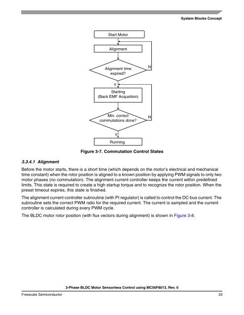
System Blocks ConceptStart <strong>Motor</strong>AlignmentAlignment timeexpired?NYStarting(Back EMF Acqusition)Min. correctcommutations done?N3.3.4.1 AlignmentYRunningFigure 3-7. Commutation <strong>Control</strong> StatesBefore the motor starts, there is a short time (which depends on the motor’s electrical and mechanicaltime constant) when the rotor position is aligned to a known position by applying PWM signals to only twomotor phases (no commutation). The alignment current controller keeps the current within predefinedlimits. This state is required to create a high startup torque and to recognize the rotor position. When thepreset timeout expires, this state is finished.The alignment current controller subroutine (with PI regulator) is called to control the DC-bus current. Thesubroutine sets the correct PWM ratio for the required current. The current is sampled and the currentcontroller is calculated during every PWM cycle.The <strong>BLDC</strong> motor rotor position (with flux vectors during alignment) is shown in Figure 3-8.3-<strong>Phase</strong> <strong>BLDC</strong> <strong>Motor</strong> <strong>Sensorless</strong> <strong>Control</strong> using <strong>MC56F8013</strong>, Rev. 0Freescale Semiconductor 33

![P-CAD EDA - [Sheet1]](https://img.yumpu.com/49470492/1/190x115/p-cad-eda-sheet1.jpg?quality=85)


