

3-Phase BLDC Motor Sensorless Control Using MC56F8013
3-Phase BLDC Motor Sensorless Control Using MC56F8013
3-Phase BLDC Motor Sensorless Control Using MC56F8013
- No tags were found...

You also want an ePaper? Increase the reach of your titles
YUMPU automatically turns print PDFs into web optimized ePapers that Google loves.
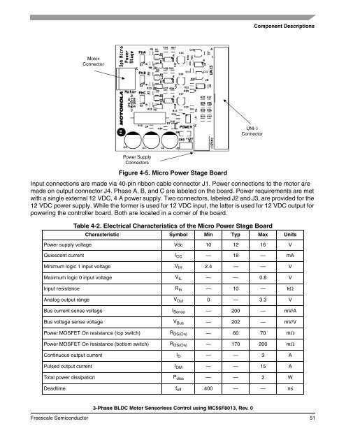
Component Descriptions<strong>Motor</strong>ConnectorUNI-3ConnectorPower SupplyConnectorsFigure 4-5. Micro Power Stage BoardInput connections are made via 40-pin ribbon cable connector J1. Power connections to the motor aremade on output connector J4. <strong>Phase</strong> A, B, and C are labeled on the board. Power requirements are metwith a single external 12 VDC, 4 A power supply. Two connectors, labeled J2 and J3, are provided for the12 VDC power supply. While the former is used for 12 VDC input, the latter is used for 12 VDC output forpowering the controller board. Both are located in a corner of the board.Table 4-2. Electrical Characteristics of the Micro Power Stage BoardCharacteristic Symbol Min Typ Max UnitsPower supply voltage Vdc 10 12 16 VQuiescent current I CC — 18 — mAMinimum logic 1 input voltage V IH 2.4 — — VMaximum logic 0 input voltage V IL — — 0.8 VInput resistance R In — 10 — kΩAnalog output range V Out 0 — 3.3 VBus current sense voltage I Sense — 200 — mV/ABus voltage sense voltage V Bus — 202 — mV/VPower MOSFET On resistance (top switch) R DS(On) — 60 70 mΩPower MOSFET On resistance (bottom switch) R DS(On) — 170 200 mΩContinuous output current I D — — 3 APulsed output current I DM — — 15 ATotal power dissipation P diss — — 2 WDeadtime t off 400 — — ns3-<strong>Phase</strong> <strong>BLDC</strong> <strong>Motor</strong> <strong>Sensorless</strong> <strong>Control</strong> using <strong>MC56F8013</strong>, Rev. 0Freescale Semiconductor 51

![P-CAD EDA - [Sheet1]](https://img.yumpu.com/49470492/1/190x115/p-cad-eda-sheet1.jpg?quality=85)


