

3-Phase BLDC Motor Sensorless Control Using MC56F8013
3-Phase BLDC Motor Sensorless Control Using MC56F8013
3-Phase BLDC Motor Sensorless Control Using MC56F8013
- No tags were found...

Create successful ePaper yourself
Turn your PDF publications into a flip-book with our unique Google optimized e-Paper software.
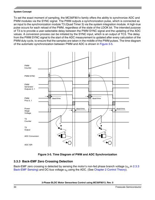
System ConceptTo set the exact moment of sampling, the MC56F801x family offers the ability to synchronize ADC andPWM modules via the SYNC signal. The PWM outputs a synchronization pulse, which is connected asan input to the synchronization module T3 (Quad Timer 3) via the system integration module. A high-truepulse occurs for each reload of the PWM, regardless of the state of the LDOK bit. The intended purposeof T3 is to provide a user-selectable delay between the PWM SYNC signal and the updating of the ADCvalues. A conversion process can be initiated by the SYNC input, which is an output of TC3. The delayfrom the PWM SYNC signal to the start of the ADC measurement is updated after every calculation of thePWM duty cycle, to ensure that the samples are taken in the middle of the PWM pulses. The time diagramof the automatic synchronization between PWM and ADC is shown in Figure 3-5.PWMCounterPWM SYNCPWMGeneratorOutputs 0, 1PWMPins 0, 1dead-timedead-timePowerStageVoltagedead-timedead-timeT3Countert1t1T3OutputADC Conversiont2t2ADC ISRFigure 3-5. Time Diagram of PWM and ADC Synchronization3.3.3 Back-EMF Zero Crossing DetectionBack-EMF zero crossing is detected by sensing the motor’s non-fed phase branch voltage (u vi in 2.3.3Back-EMF Sensing) and DC-bus voltage u d using the ADC. (See Chapter 2 <strong>Control</strong> Theory).3-<strong>Phase</strong> <strong>BLDC</strong> <strong>Motor</strong> <strong>Sensorless</strong> <strong>Control</strong> using <strong>MC56F8013</strong>, Rev. 030 Freescale Semiconductor

![P-CAD EDA - [Sheet1]](https://img.yumpu.com/49470492/1/190x115/p-cad-eda-sheet1.jpg?quality=85)


