

3-Phase BLDC Motor Sensorless Control Using MC56F8013
3-Phase BLDC Motor Sensorless Control Using MC56F8013
3-Phase BLDC Motor Sensorless Control Using MC56F8013
- No tags were found...

You also want an ePaper? Increase the reach of your titles
YUMPU automatically turns print PDFs into web optimized ePapers that Google loves.
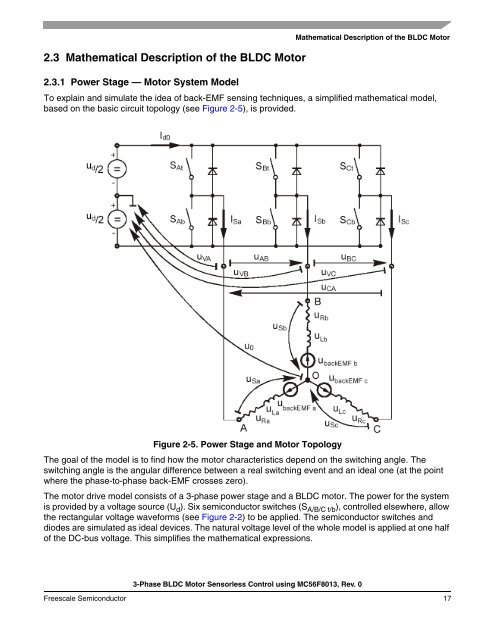
2.3 Mathematical Description of the <strong>BLDC</strong> <strong>Motor</strong>2.3.1 Power Stage — <strong>Motor</strong> System ModelMathematical Description of the <strong>BLDC</strong> <strong>Motor</strong>To explain and simulate the idea of back-EMF sensing techniques, a simplified mathematical model,based on the basic circuit topology (see Figure 2-5), is provided.Figure 2-5. Power Stage and <strong>Motor</strong> TopologyThe goal of the model is to find how the motor characteristics depend on the switching angle. Theswitching angle is the angular difference between a real switching event and an ideal one (at the pointwhere the phase-to-phase back-EMF crosses zero).The motor drive model consists of a 3-phase power stage and a <strong>BLDC</strong> motor. The power for the systemis provided by a voltage source (U d ). Six semiconductor switches (S A/B/C t/b ), controlled elsewhere, allowthe rectangular voltage waveforms (see Figure 2-2) to be applied. The semiconductor switches anddiodes are simulated as ideal devices. The natural voltage level of the whole model is applied at one halfof the DC-bus voltage. This simplifies the mathematical expressions.3-<strong>Phase</strong> <strong>BLDC</strong> <strong>Motor</strong> <strong>Sensorless</strong> <strong>Control</strong> using <strong>MC56F8013</strong>, Rev. 0Freescale Semiconductor 17

![P-CAD EDA - [Sheet1]](https://img.yumpu.com/49470492/1/190x115/p-cad-eda-sheet1.jpg?quality=85)


