

3-Phase BLDC Motor Sensorless Control Using MC56F8013
3-Phase BLDC Motor Sensorless Control Using MC56F8013
3-Phase BLDC Motor Sensorless Control Using MC56F8013
- No tags were found...

You also want an ePaper? Increase the reach of your titles
YUMPU automatically turns print PDFs into web optimized ePapers that Google loves.
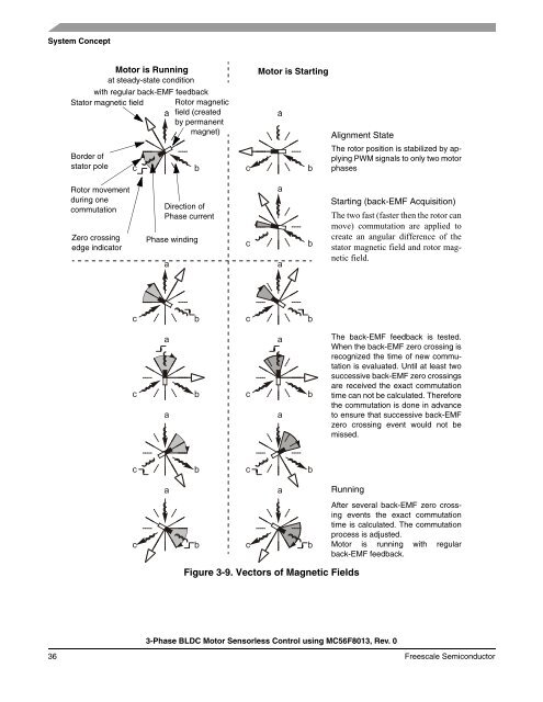
System Concept<strong>Motor</strong> is Runningat steady-state conditionwith regular back-EMF feedbackStator magnetic field Rotor magneticfield (createdby permanentmagnet)Border ofstator pole<strong>Motor</strong> is StartingAlignment StateThe rotor position is stabilized by applyingPWM signals to only two motorphasesRotor movementduring onecommutationZero crossingedge indicatorDirection of<strong>Phase</strong> current<strong>Phase</strong> windingStarting (back-EMF Acquisition)The two fast (faster then the rotor canmove) commutation are applied tocreate an angular difference of thestator magnetic field and rotor magneticfield.The back-EMF feedback is tested.When the back-EMF zero crossing isrecognized the time of new commutationis evaluated. Until at least twosuccessive back-EMF zero crossingsare received the exact commutationtime can not be calculated. Thereforethe commutation is done in advanceto ensure that successive back-EMFzero crossing event would not bemissed.RunningAfter several back-EMF zero crossingevents the exact commutationtime is calculated. The commutationprocess is adjusted.<strong>Motor</strong> is running with regularback-EMF feedback.Figure 3-9. Vectors of Magnetic Fields3-<strong>Phase</strong> <strong>BLDC</strong> <strong>Motor</strong> <strong>Sensorless</strong> <strong>Control</strong> using <strong>MC56F8013</strong>, Rev. 036 Freescale Semiconductor

![P-CAD EDA - [Sheet1]](https://img.yumpu.com/49470492/1/190x115/p-cad-eda-sheet1.jpg?quality=85)


