

3-Phase BLDC Motor Sensorless Control Using MC56F8013
3-Phase BLDC Motor Sensorless Control Using MC56F8013
3-Phase BLDC Motor Sensorless Control Using MC56F8013
- No tags were found...

Create successful ePaper yourself
Turn your PDF publications into a flip-book with our unique Google optimized e-Paper software.
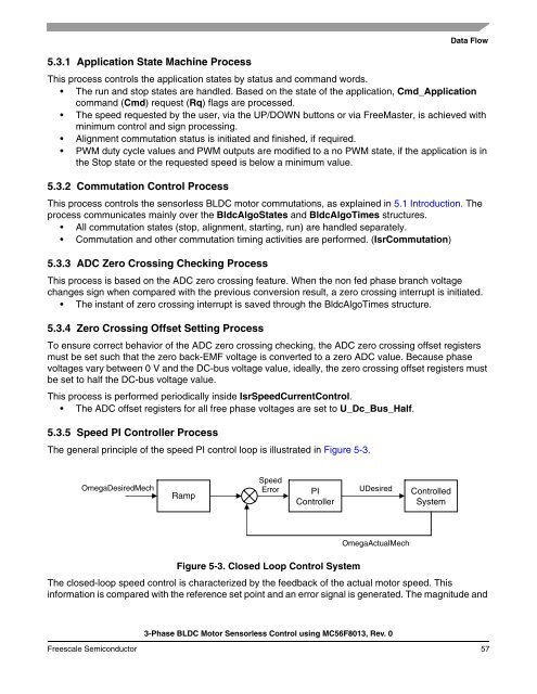
5.3.1 Application State Machine ProcessData FlowThis process controls the application states by status and command words.• The run and stop states are handled. Based on the state of the application, Cmd_Applicationcommand (Cmd) request (Rq) flags are processed.• The speed requested by the user, via the UP/DOWN buttons or via FreeMaster, is achieved withminimum control and sign processing.• Alignment commutation status is initiated and finished, if required.• PWM duty cycle values and PWM outputs are modified to a no PWM state, if the application is inthe Stop state or the requested speed is below a minimum value.5.3.2 Commutation <strong>Control</strong> ProcessThis process controls the sensorless <strong>BLDC</strong> motor commutations, as explained in 5.1 Introduction. Theprocess communicates mainly over the BldcAlgoStates and BldcAlgoTimes structures.• All commutation states (stop, alignment, starting, run) are handled separately.• Commutation and other commutation timing activities are performed. (IsrCommutation)5.3.3 ADC Zero Crossing Checking ProcessThis process is based on the ADC zero crossing feature. When the non fed phase branch voltagechanges sign when compared with the previous conversion result, a zero crossing interrupt is initiated.• The instant of zero crossing interrupt is saved through the BldcAlgoTimes structure.5.3.4 Zero Crossing Offset Setting ProcessTo ensure correct behavior of the ADC zero crossing checking, the ADC zero crossing offset registersmust be set such that the zero back-EMF voltage is converted to a zero ADC value. Because phasevoltages vary between 0 V and the DC-bus voltage value, ideally, the zero crossing offset registers mustbe set to half the DC-bus voltage value.This process is performed periodically inside IsrSpeedCurrent<strong>Control</strong>.• The ADC offset registers for all free phase voltages are set to U_Dc_Bus_Half.5.3.5 Speed PI <strong>Control</strong>ler ProcessThe general principle of the speed PI control loop is illustrated in Figure 5-3.OmegaDesiredMechRampSpeedErrorPI<strong>Control</strong>lerUDesired<strong>Control</strong>ledSystemOmegaActualMechFigure 5-3. Closed Loop <strong>Control</strong> SystemThe closed-loop speed control is characterized by the feedback of the actual motor speed. Thisinformation is compared with the reference set point and an error signal is generated. The magnitude and3-<strong>Phase</strong> <strong>BLDC</strong> <strong>Motor</strong> <strong>Sensorless</strong> <strong>Control</strong> using <strong>MC56F8013</strong>, Rev. 0Freescale Semiconductor 57

![P-CAD EDA - [Sheet1]](https://img.yumpu.com/49470492/1/190x115/p-cad-eda-sheet1.jpg?quality=85)


