

3-Phase BLDC Motor Sensorless Control Using MC56F8013
3-Phase BLDC Motor Sensorless Control Using MC56F8013
3-Phase BLDC Motor Sensorless Control Using MC56F8013
- No tags were found...

Create successful ePaper yourself
Turn your PDF publications into a flip-book with our unique Google optimized e-Paper software.
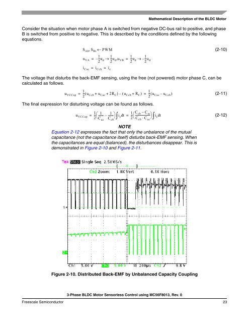
Mathematical Description of the <strong>BLDC</strong> <strong>Motor</strong>Consider the situation when motor phase A is switched from negative DC-bus rail to positive, and phaseB is switched from positive to negative. This is described by the conditions defined by the followingequations.S Ab , S Bt ← PWM1 1 1 1u VA = –--u2 d → --u2 d , u VB = --u2 d → –--u2 di Cac = =i Ccbi c(2-10)The voltage that disturbs the back-EMF sensing, using the free (not powered) motor phase C, can becalculated as follows.11u VCCap = --( u2 Ccb + u Cac + 2R C ) – ( u Ccb + R C ) = --( u2 Cac – u Ccb )(2-11)The final expression for disturbing voltage can be found as follows.1u VCCap--⎛ 1 1------- – ------- ⎞ 1ic dt-- C cb – C= = ⎛----------------------ac ⎞ ic dt(2-12)2⎝⎠ 2⎝⋅ ⎠C acC cb∫NOTEEquation 2-12 expresses the fact that only the unbalance of the mutualcapacitance (not the capacitance itself) disturbs back-EMF sensing. Whenthe capacitances are equal (balanced), the disturbances disappear. This isdemonstrated in Figure 2-10 and Figure 2-11.C cbC ac∫Figure 2-10. Distributed Back-EMF by Unbalanced Capacity Coupling3-<strong>Phase</strong> <strong>BLDC</strong> <strong>Motor</strong> <strong>Sensorless</strong> <strong>Control</strong> using <strong>MC56F8013</strong>, Rev. 0Freescale Semiconductor 23

![P-CAD EDA - [Sheet1]](https://img.yumpu.com/49470492/1/190x115/p-cad-eda-sheet1.jpg?quality=85)


