

3-Phase BLDC Motor Sensorless Control Using MC56F8013
3-Phase BLDC Motor Sensorless Control Using MC56F8013
3-Phase BLDC Motor Sensorless Control Using MC56F8013
- No tags were found...

Create successful ePaper yourself
Turn your PDF publications into a flip-book with our unique Google optimized e-Paper software.
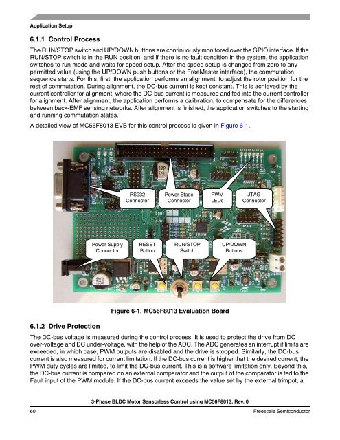
Application Setup6.1.1 <strong>Control</strong> ProcessThe RUN/STOP switch and UP/DOWN buttons are continuously monitored over the GPIO interface. If theRUN/STOP switch is in the RUN position, and if there is no fault condition in the system, the applicationswitches to run mode and waits for speed setup. After the speed setup is changed from zero to anypermitted value (using the UP/DOWN push buttons or the FreeMaster interface), the commutationsequence starts. For this, first, the application performs an alignment, to adjust the rotor position for therest of commutation. During alignment, the DC-bus current is kept constant. This is achieved by thecurrent controller for alignment, where the DC-bus current is measured and fed into the current controllerfor alignment. After alignment, the application performs a calibration, to compensate for the differencesbetween back-EMF sensing networks. After alignment is finished, the application switches to the startingand running commutation states.A detailed view of <strong>MC56F8013</strong> EVB for this control process is given in Figure 6-1.RS232ConnectorPower StageConnectorPWMLEDsJTAGConnectorPower SupplyConnectorRESETButtonRUN/STOPSwitchUP/DOWNButtons6.1.2 Drive ProtectionFigure 6-1. <strong>MC56F8013</strong> Evaluation BoardThe DC-bus voltage is measured during the control process. It is used to protect the drive from DCover-voltage and DC under-voltage, with the help of the ADC. The ADC generates an interrupt if limits areexceeded, in which case, PWM outputs are disabled and the drive is stopped. Similarly, the DC-buscurrent is also measured for current limitation. If the DC-bus current is higher that the desired current, thePWM duty cycles are limited, to limit the DC-bus current. This is a software limitation only. Beyond this,the DC-bus current is compared on an external comparator and the output of the comparator is fed to theFault input of the PWM module. If the DC-bus current exceeds the value set by the external trimpot, a3-<strong>Phase</strong> <strong>BLDC</strong> <strong>Motor</strong> <strong>Sensorless</strong> <strong>Control</strong> using <strong>MC56F8013</strong>, Rev. 060 Freescale Semiconductor

![P-CAD EDA - [Sheet1]](https://img.yumpu.com/49470492/1/190x115/p-cad-eda-sheet1.jpg?quality=85)


