

3-Phase BLDC Motor Sensorless Control Using MC56F8013
3-Phase BLDC Motor Sensorless Control Using MC56F8013
3-Phase BLDC Motor Sensorless Control Using MC56F8013
- No tags were found...

You also want an ePaper? Increase the reach of your titles
YUMPU automatically turns print PDFs into web optimized ePapers that Google loves.
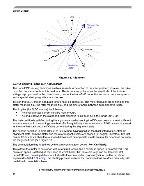
System Concept3.3.4.2 Starting (Back-EMF Acquisition)Figure 3-8. AlignmentThe back-EMF sensing technique enables sensorless detection of the rotor position; however, the drivemust first be started without this feedback. This is necessary, because the amplitude of the inducedvoltage is proportional to the motor speed; hence, the back-EMF cannot be sensed at very low speeds,and a special startup algorithm must be used.To start the <strong>BLDC</strong> motor, adequate torque must be generated. The motor torque is proportional to thestator magnetic flux, the rotor magnetic flux, and the sine of angle between both magnetic fluxes.This implies (for <strong>BLDC</strong> motors) the following:• The level of phase current must be high enough.• The angle between the stator and rotor magnetic fields must be in the range 90° ± 30°.The first condition is satisfied during the alignment state by keeping the DC-bus current at a level sufficientto start the motor. In the starting state (back-EMF acquisition), the same value of PWM duty cycle is usedas the one that stabilized the DC-bus current during the alignment state.The second condition is more difficult to fulfil without having position feedback information. After thealignment state, both the stator and the rotor magnetic fields are aligned (0° angle). Therefore, two fastcommutations (faster then the rotor can follow) must be applied to create an angular difference betweenthe magnetic fields (see Figure 3-9).The commutation time is defined by the start commutation period (Per_CmtStart).This allows the motor to be started with a required torque and a minimum speed to be achieved. Thisminimum speed is defined as the speed at which back-EMF zero crossings can be detected. Untilback-EMF zero crossing detection is locked to the commutation process (defined as the run state,explained in 3.3.4.3 Running), the starting process ensures that commutations are done manually, withpredefined commutation times.3-<strong>Phase</strong> <strong>BLDC</strong> <strong>Motor</strong> <strong>Sensorless</strong> <strong>Control</strong> using <strong>MC56F8013</strong>, Rev. 034 Freescale Semiconductor

![P-CAD EDA - [Sheet1]](https://img.yumpu.com/49470492/1/190x115/p-cad-eda-sheet1.jpg?quality=85)


