

3-Phase BLDC Motor Sensorless Control Using MC56F8013
3-Phase BLDC Motor Sensorless Control Using MC56F8013
3-Phase BLDC Motor Sensorless Control Using MC56F8013
- No tags were found...

You also want an ePaper? Increase the reach of your titles
YUMPU automatically turns print PDFs into web optimized ePapers that Google loves.
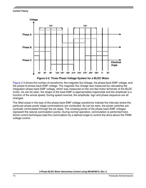
<strong>Control</strong> TheoryVoltage120120<strong>Phase</strong> A<strong>Phase</strong> B<strong>Phase</strong> CElectricalAngle30 60 90120150 180 210 240 270 300 330030Figure 2-2. Three <strong>Phase</strong> Voltage System for a <strong>BLDC</strong> <strong>Motor</strong>Figure 2-3 shows the number of waveforms, the magnetic flux linkage, the phase back-EMF voltage, andthe phase-to-phase back-EMF voltage. The magnetic flux linkage was measured by calculating theintegration phase back-EMF voltage, which was measured on the non-fed motor terminals of the <strong>BLDC</strong>motor. As can be seen, the shape of the back-EMF is approximately trapezoidal and the amplitude is afunction of the actual speed. During speed reversal, the amplitude, sign and phase sequence are allchanged.The filled areas in the tops of the phase back-EMF voltage waveforms indicate the intervals where theparticular phase power stage commutations are conducted. As can be seen, the power switches arecyclically commutated through the six steps. The crossing points of the phase back-EMF voltagesrepresent the natural commutation points. During normal operation, commutation is performed here.Some control techniques lead the commutation by a defined angle to control the drive above the PWMvoltage control.3-<strong>Phase</strong> <strong>BLDC</strong> <strong>Motor</strong> <strong>Sensorless</strong> <strong>Control</strong> using <strong>MC56F8013</strong>, Rev. 014 Freescale Semiconductor

![P-CAD EDA - [Sheet1]](https://img.yumpu.com/49470492/1/190x115/p-cad-eda-sheet1.jpg?quality=85)


