

CUVX Design Report - the AOE home page - Virginia Tech
CUVX Design Report - the AOE home page - Virginia Tech
CUVX Design Report - the AOE home page - Virginia Tech

Create successful ePaper yourself
Turn your PDF publications into a flip-book with our unique Google optimized e-Paper software.
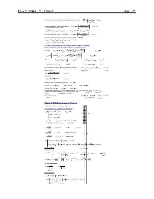
<strong>CUVX</strong> <strong>Design</strong> – VT Team 2 Page 109V DDeckhouse decks impacted by propulsion and generator inlet/exhaust: N DIE ceilH . LWLDK B.3Hull decks impacted by propulsion inlet/exhaust:(assumes 2m inner bottom in MB)N HPIED 10 H MBreq 1m .floorNH HPIE = 3HANGDKH MB D 10 N . HANGDK H HANGDK 1m . H MB = 10.624 m H MBreq = 7.59 mD 10 H MBreq 1m .Hull decks impacted by generator inlet/exhaust: N HGIE floorNH HGIE = 3HANGDKTotal Inlet/exhaust arrangeable area required (assumes 2 SSG outside MB):A HIE 1.4. N . HPIE A PIE N . HGIE A GIE A HIE = 673.606 ft 2A DIE 0m . 2 (side or stern exhaust)N DIE = 12g. Manning, o<strong>the</strong>r requirements, constraints and margins, constant for all designs:Manning, where N O and N E stand for number of officers and enlisted, respectively:N SSG W P W VP V FL V DCManShip= 1 N OShip 3 ceil N prop5 15.lton 80000.ft 3N OShip 48WN EShip ceil CManShip N . prop 6 N . P W VP V FL V. DSSG 3N10.lton 4450.ft 3EShip 534.1CManAir= 1 N OAir ceil .MT W F23 N OAir 19 N O N OAir N OShip N O = 67N EAir ceil CManAir. 1.5 . W F23 N EAir 297 N E N EAir N EShip N E = 831MTN T defines <strong>the</strong> total crew size, N A <strong>the</strong> additional accommodations: N T N EShip N OShip N EAir N OAir N T = 898Repair - MOP14: N A ceil .1. N TN A = 90CManShip CManAirVOP 142DC - MOP22:CManShip CManAirVOP 222VOP 14= 1VOP 22= 1Ballast type (1 for compensated, 2 o<strong>the</strong>rwise): BAL TYP 1Margins: KG MARG1.0. m power: PMF 1.1 weight: WMF 0.1electrical load: EDMF 1.1 EFMF 1.1 E24MF 1.1Hull material (will be used for hull structure weight calculation in <strong>the</strong> weight section later; 1.0 for OS or 0.93 forHTS/HSS) and deckhouse material (1 for aluminum and 2 for steel): C HMAT 0.93 C DHMAT 2V ADH ( B 2 . T) ..6. LWL . 1 . mHull Type(ADH or Conventional): VOP 200.0 if HullForm 5 V ADH = 5.531. 10 3 m 3Hull=1DP 22o<strong>the</strong>rwiseVOP 20= 1Module 3 - Ship Resistance and Poweringi 1, 2.. 12 V ii2 . . knt V 10V e V 11V S3a. Hull Surface Area, Coefficients and Dimensions:S SD 10. ft 2 if SON TYP 01400. ft 2 if SON TYP 180. ft 2 if SON TYP 2S SD = 10 ft 2S SDA BTA BT = 2ft 2 (bulb section area at FP)5L R 1 C . P LWL L R = 63.989 m (Run length)11 22 43 64 85 10V = 6 127 148 169 1810 2011 2012 24kntC VV FLCLWL 3 V = 3.008.10 3 T F T T F = 7.085 mh BA TA BTπBT . . C X5h B = 0.243 m (height of bulb center)A T = 39.103 m 2 (transom area)C W = 0.863S i280.29. V . ift. sec 81540. ft 2 . 2R FS S SD if DP 11LWL. ( 2 . T B). C M .453 .4425. C B .2862. C M .003467 B A. . .3696.C W 2.38. BTS SD o<strong>the</strong>rwiseTC B3b. Viscous DragCoefficient of friction:V iR Ni LWL. 0.075C Fiυ SWS 1= 7.547. 10 4 ft 2(ITTC) (ATTC) R ilog R Ni 2 2 C fi0.066log R Ni 2.03 2V iLWL.22284 .92497T Bformfac 1.03 .93. . .521448.95 C P 1 C P .05 .6906 S. .2.7.SDLWL L R S 13c. Wave Making DragV iV iFn Vi13V . FL gFn ig.LWLFS and US GeosimC RUSi .0279. 2Fn Vi .0438. Fn Vi .0174C RFSi 0.0411. 3Fn Vi 0.1019. 2Fn Vi 0.0858 . Fn 0.0225 Fn Vi if < 1.05 Vi1.6912Fn . Vi0.0005 e o<strong>the</strong>rwise


