

CUVX Design Report - the AOE home page - Virginia Tech
CUVX Design Report - the AOE home page - Virginia Tech
CUVX Design Report - the AOE home page - Virginia Tech

You also want an ePaper? Increase the reach of your titles
YUMPU automatically turns print PDFs into web optimized ePapers that Google loves.
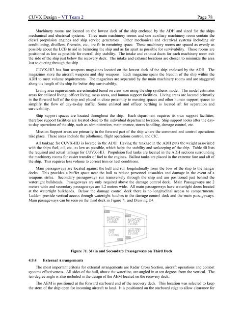
<strong>CUVX</strong> <strong>Design</strong> – VT Team 2 Page 78Machinery rooms are located on <strong>the</strong> lowest deck of <strong>the</strong> ship enclosed by <strong>the</strong> ADH and sized for <strong>the</strong> shipsmechanical and electrical systems. Three main machinery rooms and one auxiliary machinery room contain <strong>the</strong>diesel propulsion engines and ship service generators. O<strong>the</strong>r mechanical and electrical systems including airconditioning, distillers, firemain, etc., are fit in remaining space. These machinery rooms are spaced as evenly aspossible about <strong>the</strong> LCB to aid in balancing <strong>the</strong> ship and as far apart as possible for survivability. These rooms arepositioned as low as possible for overall ship stability. The intake and exhaust ducts for each machinery room exit<strong>the</strong> side of <strong>the</strong> ship just below <strong>the</strong> recovery deck. The intake and exhaust locations are chosen to minimize <strong>the</strong> arealost to ducting through <strong>the</strong> ship.<strong>CUVX</strong>-HI3 has four weapons magazines located on <strong>the</strong> lowest deck of <strong>the</strong> ship enclosed by <strong>the</strong> ADH. Themagazines store <strong>the</strong> aircraft weapons and ship weapons. Each magazine spans <strong>the</strong> breadth of <strong>the</strong> ship within <strong>the</strong>ADH to meet volume requirements. The magazines are separated by <strong>the</strong> main machinery rooms and are staggeredalong <strong>the</strong> length of <strong>the</strong> ship for better ship survivability.Living area requirements are estimated based on crew size using <strong>the</strong> ship syn<strong>the</strong>sis model. The model estimatesareas for enlisted living, officer living, mess areas, and human support facilities. Living areas are located primarilyin <strong>the</strong> forward half of <strong>the</strong> ship and placed in close proximity to messing spaces and o<strong>the</strong>r human support spaces tosimplify <strong>the</strong> flow of day-to-day traffic. Some enlisted and officer berthing is located aft for separation andsurvivability.Ship support spaces are located throughout <strong>the</strong> ship. Each department requires its own support facilities;<strong>the</strong>refore support facilities are located close to <strong>the</strong> individual department location. Ship support looks after <strong>the</strong> dayto-dayoperations of <strong>the</strong> ship, such as administration, maintenance, stores handling, damage control, etc.Mission Support areas are primarily in <strong>the</strong> forward part of <strong>the</strong> ship where <strong>the</strong> command and control operationstake place. These areas include <strong>the</strong> pilothouse, flight operations control, and CIC.All tankage for <strong>CUVX</strong>-HI3 is located in <strong>the</strong> ADH. Having <strong>the</strong> tankage in <strong>the</strong> ADH puts <strong>the</strong> weight associatedwith <strong>the</strong> ships fuel, oil, etc., as low as possible, which helps <strong>the</strong> stability and seakeeping of <strong>the</strong> ship. Table 40 lists<strong>the</strong> required and actual tankage for <strong>CUVX</strong>-HI3. Propulsion fuel tanks are located in <strong>the</strong> ADH sections surrounding<strong>the</strong> machinery rooms for easier transfer of fuel to <strong>the</strong> engines. Ballast tanks are placed in <strong>the</strong> extreme fore and aft of<strong>the</strong> ship. This requires less volume to correct trim or heel conditions.Main passageways are located against <strong>the</strong> hull and run longitudinally from <strong>the</strong> bow of <strong>the</strong> ship to <strong>the</strong> hangardecks. This provides a buffer space near <strong>the</strong> hull to reduce personnel casualties and damage in <strong>the</strong> event of aweapons strike. Secondary passageways run transversely through <strong>the</strong> ship and are positioned just behind <strong>the</strong>watertight bulkheads. Passageways are only required above <strong>the</strong> damage control deck. Main Passageways are 2meters wide and secondary passageways are 1.2 meters wide. All main passageways have watertight doors locatedat <strong>the</strong> watertight bulkheads. Below <strong>the</strong> damage control deck <strong>the</strong>re is no longitudinal access to compartments.Ladders provide vertical access through watertight hatches to <strong>the</strong> damage control deck and <strong>the</strong> main passageways.Main passageways can be seen on <strong>the</strong> third deck in Figure 71 and Drawing D4.Figure 71. Main and Secondary Passageways on Third Deck4.9.4 External ArrangementsThe most important criteria for external arrangements are Radar Cross Section, aircraft operations and combatsystems effectiveness. All sides of <strong>the</strong> hull, above <strong>the</strong> waterline, are angled in at ten degrees from <strong>the</strong> vertical. Theten-degree angle is also included in <strong>the</strong> design of <strong>the</strong> AEM located on <strong>the</strong> recovery deck.The AEM is positioned at <strong>the</strong> forward starboard end of <strong>the</strong> recovery deck. This location was selected to keep<strong>the</strong> stern of <strong>the</strong> ship open for incoming aircraft to land. It is positioned on <strong>the</strong> starboard edge to allow clearance for


