Master Thesis - Fachbereich Informatik
Master Thesis - Fachbereich Informatik
Master Thesis - Fachbereich Informatik
Create successful ePaper yourself
Turn your PDF publications into a flip-book with our unique Google optimized e-Paper software.
14 CHAPTER 2. TECHNICAL BACKGROUND<br />
physical parameters of the camera. At this stage, one can distinguish between intrinsic<br />
and extrinsic parameters [24].<br />
Intrinsic Parameters The intrinsic parameters describe the projection of a point in the<br />
camera frame onto the image plane, i.e. the transformation of camera coordinates into<br />
image coordinates. This transformation extends the ideal perspective camera model introduced<br />
in the previous section with respect to properties of real CCD cameras. One can<br />
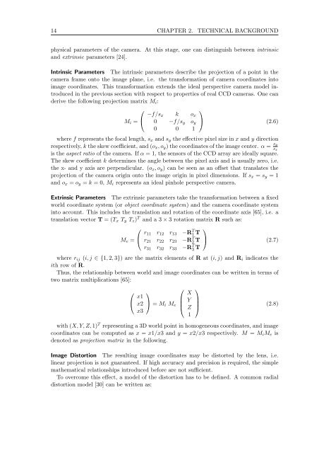
derive the following projection matrix Mi:<br />
⎛<br />
⎞<br />
−f/sx k ox<br />
Mi = ⎝ 0 −f/sy oy ⎠ (2.6)<br />
0 0 1<br />
where f represents the focal length, sx and sy theeffectivepixelsizeinxand y direction<br />
respectively, k the skew coefficient, and (ox,oy) the coordinates of the image center. α = sy<br />
is the aspect ratio of the camera. If α = 1, the sensors of the CCD array are ideally square.<br />
The skew coefficient k determines the angle between the pixel axis and is usually zero, i.e.<br />
the x- and y axis are perpendicular. (ox,oy) can be seen as an offset that translates the<br />
projection of the camera origin onto the image origin in pixel dimensions. If sx = sy =1<br />
and ox = oy = k =0,Mi represents an ideal pinhole perspective camera.<br />
Extrinsic Parameters The extrinsic parameters take the transformation between a fixed<br />
world coordinate system (or object coordinate system) and the camera coordinate system<br />
into account. This includes the translation and rotation of the coordinate axis [65], i.e. a<br />
translation vector T =(Tx Ty Tz) T and a 3 × 3 rotation matrix R such as:<br />
⎛<br />
Me = ⎝<br />
r11 r12 r13 −R T 1 T<br />
r21 r22 r23 −R T 2 T<br />
r31 r32 r33 −R T 3 T<br />
⎞<br />
sx<br />
⎠ (2.7)<br />
where rij (i, j ∈{1, 2, 3}) are the matrix elements of R at (i, j) andRi indicates the<br />
ith row of R.<br />
Thus, the relationship between world and image coordinates can be written in terms of<br />
two matrix multiplications [65]:<br />
⎛<br />
⎝<br />
x1<br />
x2<br />
x3<br />
⎞<br />
⎠ = Mi Me<br />
⎛<br />
⎜<br />
⎝<br />
X<br />
Y<br />
Z<br />
1<br />
⎞<br />
⎟<br />
⎠<br />
(2.8)<br />
with (X, Y, Z, 1) T representing a 3D world point in homogeneous coordinates, and image<br />
coordinates can be computed as x = x1/x3 andy = x2/x3 respectively. M = MiMe is<br />
denoted as projection matrix in the following.<br />
Image Distortion The resulting image coordinates may be distorted by the lens, i.e.<br />
linear projection is not guaranteed. If high accuracy and precision is required, the simple<br />
mathematical relationships introduced before are not sufficient.<br />
To overcome this effect, a model of the distortion has to be defined. A common radial<br />
distortion model [30] can be written as:


