

Master Thesis - Fachbereich Informatik
Master Thesis - Fachbereich Informatik
Master Thesis - Fachbereich Informatik

Create successful ePaper yourself
Turn your PDF publications into a flip-book with our unique Google optimized e-Paper software.
3.3. ILLUMINATION 45<br />
(a) (b) (c)<br />
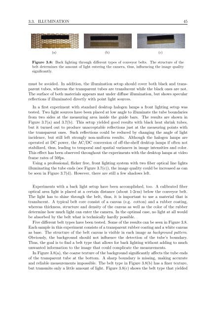
Figure 3.8: Back lighting through different types of conveyor belts. The structure of the<br />
belt determines the amount of light entering the camera, thus, influencing the image quality<br />
significantly.<br />
must be avoided. In addition, the illumination setup should cover both black and transparent<br />
tubes, whereas the transparent tubes are translucent while the black ones are not.<br />
The surface of both materials appears mat under diffuse illumination, but shows specular<br />
reflections if illuminated directly with point light sources.<br />
In a first experiment with standard desktop halogen lamps a front lighting setup was<br />
tested. Two light sources have been placed at low angle to illuminate the tube boundaries<br />
from two sides at the measuring area inside the guide bars. The results are shown in<br />
Figure 3.7(a) and 3.7(b). This setup yielded good results with black heat shrink tubes,<br />
but it turned out to produce unacceptable reflections just at the measuring points with<br />
the transparent ones. Such reflections could be reduced by changing the angle of light<br />
incidence, but still left strongly non-uniform results. Although the halogen lamps are<br />
operated at DC power, the AC/DC conversion of off-the-shelf desktop lamps if often not<br />
stabilized, thus, leading to temporal and spatial variances in image intensities and color.<br />
This effect has been observed throughout the experiments with the desktop lamps at video<br />
frame rates of 50fps.<br />
Using a professional, flicker free, front lighting system with two fiber optical line lights<br />
illuminating the tube ends (see Figure 3.7(c)), the image quality could be increased as can<br />
be seen in Figure 3.7(d). However, there are still a few shadows left.<br />
Experiments with a back light setup have been accomplished, too. A calibrated fiber<br />
optical area light is placed at a certain distance (about 1-2cm) below the conveyor belt.<br />
The light has to shine through the belt, thus, it is important to use a material that is<br />
translucent. A typical belt core consist of a canvas (e.g. cotton) and a rubber coating,<br />
whereas thickness, structure and density of the canvas as well as the color of the rubber<br />
determine how much light can enter the camera. In the optimal case, no light at all would<br />
be absorbed by the belt what is technically hardly possible.<br />
Five different belt types have been tested. Some of the results can be seen in Figure 3.8.<br />
Each sample in this experiment consists of a transparent rubber coating and a white canvas<br />
as base. The structure of the belt canvas is visible in each image as background pattern.<br />
Obviously, the background should not influence the detection of the tube’s boundary.<br />
Thus, the goal is to find a belt type that allows for back lighting without adding to much<br />
unwanted information to the image that could complicate the measurements.<br />
In Figure 3.8(a), the coarse texture of the background significantly affects the tube ends<br />
of the transparent tube at the bottom. A sharp boundary is missing, making accurate<br />
and reliable measurements impossible. The belt type in Figure 3.8(b) has a finer texture,<br />
but transmits only a little amount of light. Figure 3.8(c) shows the belt type that yielded


