

Master Thesis - Fachbereich Informatik
Master Thesis - Fachbereich Informatik
Master Thesis - Fachbereich Informatik

You also want an ePaper? Increase the reach of your titles
YUMPU automatically turns print PDFs into web optimized ePapers that Google loves.
48 CHAPTER 3. HARDWARE CONFIGURATION<br />
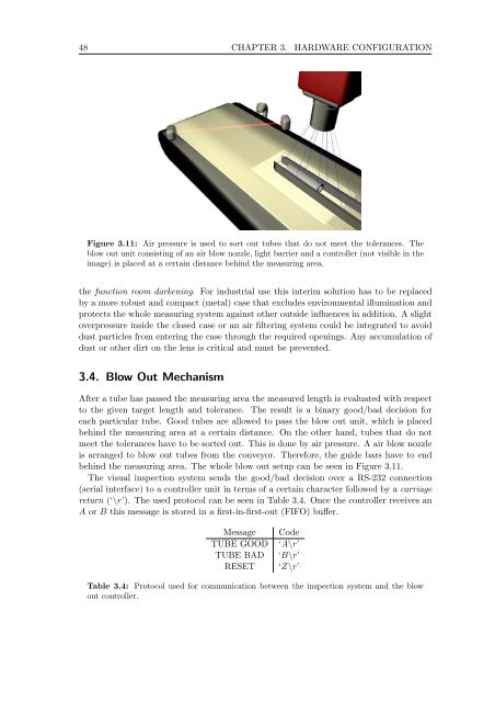
Figure 3.11: Air pressure is used to sort out tubes that do not meet the tolerances. The<br />
blow out unit consisting of an air blow nozzle, light barrier and a controller (not visible in the<br />
image) is placed at a certain distance behind the measuring area.<br />
the function room darkening. For industrial use this interim solution has to be replaced<br />
by a more robust and compact (metal) case that excludes environmental illumination and<br />
protects the whole measuring system against other outside influences in addition. A slight<br />
overpressure inside the closed case or an air filtering system could be integrated to avoid<br />
dust particles from entering the case through the required openings. Any accumulation of<br />
dust or other dirt on the lens is critical and must be prevented.<br />
3.4. Blow Out Mechanism<br />
After a tube has passed the measuring area the measured length is evaluated with respect<br />
to the given target length and tolerance. The result is a binary good/bad decision for<br />
each particular tube. Good tubes are allowed to pass the blow out unit, which is placed<br />
behind the measuring area at a certain distance. On the other hand, tubes that do not<br />
meetthetoleranceshavetobesortedout. Thisisdonebyairpressure. Aairblownozzle<br />
is arranged to blow out tubes from the conveyor. Therefore, the guide bars have to end<br />
behind the measuring area. The whole blow out setup can be seen in Figure 3.11.<br />
The visual inspection system sends the good/bad decision over a RS-232 connection<br />
(serial interface) to a controller unit in terms of a certain character followed by a carriage<br />
return (‘\r’). The used protocol can be seen in Table 3.4. Once the controller receives an<br />
A or B this message is stored in a first-in-first-out (FIFO) buffer.<br />
Message Code<br />
TUBE GOOD ‘A\r’<br />
TUBE BAD ‘B\r’<br />
RESET ‘Z\r’<br />
Table 3.4: Protocol used for communication between the inspection system and the blow<br />
out controller.


