Design, Fabrication and Characterization of a Microwave Resonator ...
Design, Fabrication and Characterization of a Microwave Resonator ...
Design, Fabrication and Characterization of a Microwave Resonator ...

Create successful ePaper yourself
Turn your PDF publications into a flip-book with our unique Google optimized e-Paper software.
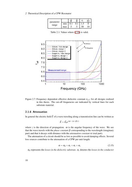
2 Theoretical Description <strong>of</strong> a CPW <strong>Resonator</strong>parameterrangeSWSfHε r f T Emin 0.1 0.1 1.5 0max 5 5 50 10Table 2.1: Values where (2.14) is valid.Figure 2.7: Frequency dependent effective dielectric constant ε e f f for all designs realizedin this thesis. The cut-<strong>of</strong>f frequencies are indicated by vertical lines for eachsubstrate material.2.1.6 AttenuationIn general the electric field ⃗E <strong>of</strong> a wave traveling along a transmission line can be written as⃗E = ⃗E 0 e (ωt−(α+iβ)z)where z is the direction <strong>of</strong> propagation. ω is the angular frequency <strong>of</strong> the wave. We seethat the wave travels with the phase constant β corresponding to the wavelength (imaginarypart) <strong>and</strong> that it decays with distance with the attenuation constant α (real part).The attenuation <strong>of</strong> a circuit should be as low as possible to avoid damping effects. Severalloss sources contribute to the attenuation <strong>of</strong> a CPW per unit length:α = α d + α c + α r + α s (2.15)α d represents the losses in the dielectric substrate. α c denotes the losses in the conductor10