Design, Fabrication and Characterization of a Microwave Resonator ...
Design, Fabrication and Characterization of a Microwave Resonator ...
Design, Fabrication and Characterization of a Microwave Resonator ...

You also want an ePaper? Increase the reach of your titles
YUMPU automatically turns print PDFs into web optimized ePapers that Google loves.
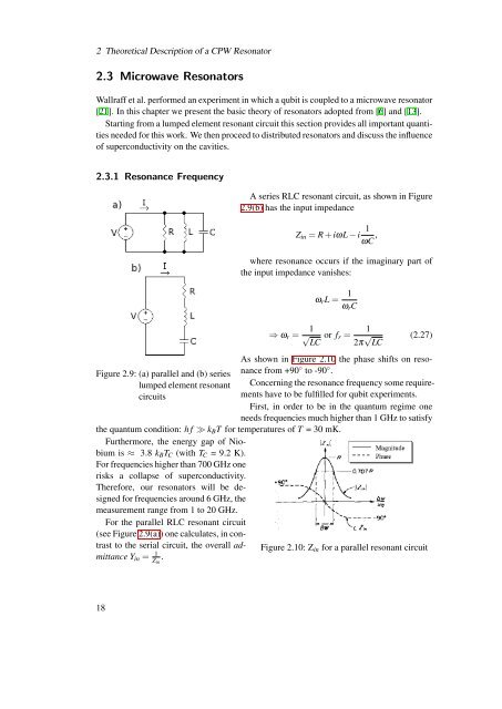
2 Theoretical Description <strong>of</strong> a CPW <strong>Resonator</strong>2.3 <strong>Microwave</strong> <strong>Resonator</strong>sWallraff et al. performed an experiment in which a qubit is coupled to a microwave resonator[21]. In this chapter we present the basic theory <strong>of</strong> resonators adopted from [6] <strong>and</strong> [13].Starting from a lumped element resonant circuit this section provides all important quantitiesneeded for this work. We then proceed to distributed resonators <strong>and</strong> discuss the influence<strong>of</strong> superconductivity on the cavities.2.3.1 Resonance FrequencyFigure 2.9: (a) parallel <strong>and</strong> (b) serieslumped element resonantcircuitsA series RLC resonant circuit, as shown in Figure2.9(b) has the input impedance1Z in = R + iωL − iωC ,where resonance occurs if the imaginary part <strong>of</strong>the input impedance vanishes:ω r L = 1ω r C⇒ ω r = 1 √LCor f r =12π √ LC(2.27)As shown in Figure 2.10 the phase shifts on resonancefrom +90 ◦ to -90 ◦ .Concerning the resonance frequency some requirementshave to be fulfilled for qubit experiments.First, in order to be in the quantum regime oneneeds frequencies much higher than 1 GHz to satisfythe quantum condition: h f ≫ k B T for temperatures <strong>of</strong> T = 30 mK.Furthermore, the energy gap <strong>of</strong> Niobiumis ≈ 3.8 k B T C (with T C = 9.2 K).For frequencies higher than 700 GHz onerisks a collapse <strong>of</strong> superconductivity.Therefore, our resonators will be designedfor frequencies around 6 GHz, themeasurement range from 1 to 20 GHz.For the parallel RLC resonant circuit(see Figure 2.9(a)) one calculates, in contrastto the serial circuit, the overall admittanceY in = 1Z in.Figure 2.10: Z in for a parallel resonant circuit18