Design, Fabrication and Characterization of a Microwave Resonator ...
Design, Fabrication and Characterization of a Microwave Resonator ...
Design, Fabrication and Characterization of a Microwave Resonator ...
You also want an ePaper? Increase the reach of your titles
YUMPU automatically turns print PDFs into web optimized ePapers that Google loves.
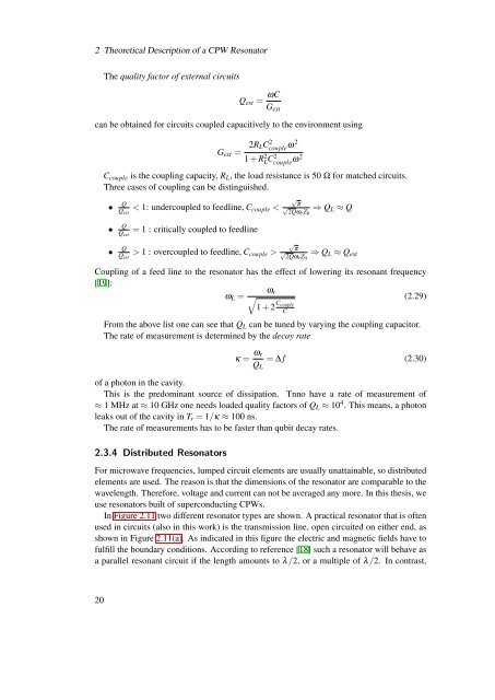
2 Theoretical Description <strong>of</strong> a CPW <strong>Resonator</strong>The quality factor <strong>of</strong> external circuitsQ ext = ωCG extcan be obtained for circuits coupled capacitively to the environment usingG ext =2R LCcouple 2 ω21 + R 2 L C2 couple ω2C couple is the coupling capacity, R L , the load resistance is 50 Ω for matched circuits.Three cases <strong>of</strong> coupling can be distinguished.• Q√Q ext< 1: undercoupled to feedline, C couple < √ π2Qωr⇒ QZ L ≈ Q0• QQ ext= 1 : critically coupled to feedline• Q√Q ext> 1 : overcoupled to feedline, C couple > √ π2Qωr⇒ QZ L ≈ Q ext0Coupling <strong>of</strong> a feed line to the resonator has the effect <strong>of</strong> lowering its resonant frequency[19]:ω rω L = √(2.29)1 + 2 C coupleCFrom the above list one can see that Q L can be tuned by varying the coupling capacitor.The rate <strong>of</strong> measurement is determined by the decay rateκ = ω rQ L= ∆ f (2.30)<strong>of</strong> a photon in the cavity.This is the predominant source <strong>of</strong> dissipation. Tnno have a rate <strong>of</strong> measurement <strong>of</strong>≈ 1 MHz at ≈ 10 GHz one needs loaded quality factors <strong>of</strong> Q L ≈ 10 4 . This means, a photonleaks out <strong>of</strong> the cavity in T r = 1/κ ≈ 100 ns.The rate <strong>of</strong> measurements has to be faster than qubit decay rates.2.3.4 Distributed <strong>Resonator</strong>sFor microwave frequencies, lumped circuit elements are usually unattainable, so distributedelements are used. The reason is that the dimensions <strong>of</strong> the resonator are comparable to thewavelength. Therefore, voltage <strong>and</strong> current can not be averaged any more. In this thesis, weuse resonators built <strong>of</strong> superconducting CPWs.In Figure 2.11 two different resonator types are shown. A practical resonator that is <strong>of</strong>tenused in circuits (also in this work) is the transmission line, open circuited on either end, asshown in Figure 2.11(a). As indicated in this figure the electric <strong>and</strong> magnetic fields have t<strong>of</strong>ulfill the boundary conditions. According to reference [18] such a resonator will behave asa parallel resonant circuit if the length amounts to λ/2, or a multiple <strong>of</strong> λ/2. In contrast,20


