Design, Fabrication and Characterization of a Microwave Resonator ...
Design, Fabrication and Characterization of a Microwave Resonator ...
Design, Fabrication and Characterization of a Microwave Resonator ...
Create successful ePaper yourself
Turn your PDF publications into a flip-book with our unique Google optimized e-Paper software.
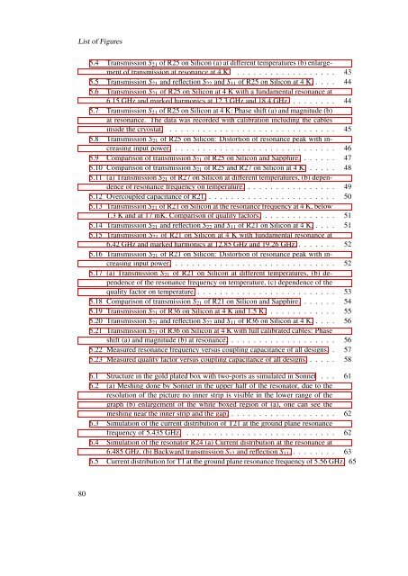
List <strong>of</strong> Figures5.4 Transmission S 21 <strong>of</strong> R25 on Silicon (a) at different temperatures (b) enlargement<strong>of</strong> transmission at resonance at 4 K. . . . . . . . . . . . . . . . . . . 435.5 Transmission S 21 <strong>and</strong> reflection S 22 <strong>and</strong> S 11 <strong>of</strong> R25 on Silicon at 4 K. . . . . 445.6 Transmission S 21 <strong>of</strong> R25 on Silicon at 4 K with a fundamental resonance at6.15 GHz <strong>and</strong> marked harmonics at 12.3 GHz <strong>and</strong> 18.4 GHz. . . . . . . . . 445.7 Transmission S 21 <strong>of</strong> R25 on Silicon at 4 K: Phase shift (a) <strong>and</strong> magnitude (b)at resonance. The data was recorded with calibration including the cablesinside the cryostat. . . . . . . . . . . . . . . . . . . . . . . . . . . . . . . 455.8 Transmission S 21 <strong>of</strong> R25 on Silicon: Distortion <strong>of</strong> resonance peak with increasinginput power. . . . . . . . . . . . . . . . . . . . . . . . . . . . . . 465.9 Comparison <strong>of</strong> transmission S 21 <strong>of</strong> R25 on Silicon <strong>and</strong> Sapphire. . . . . . . 475.10 Comparison <strong>of</strong> transmission S 21 <strong>of</strong> R25 <strong>and</strong> R27 on Silicon at 4 K. . . . . . 485.11 (a) Transmission S 21 <strong>of</strong> R27 on Silicon at different temperatures, (b) dependence<strong>of</strong> resonance frequency on temperature. . . . . . . . . . . . . . . . . 495.12 Overcoupled capacitance <strong>of</strong> R21. . . . . . . . . . . . . . . . . . . . . . . . 505.13 Transmission S 21 <strong>of</strong> R21 on Silicon at the resonance frequency at 4 K, below1.3 K <strong>and</strong> at 17 mK. Comparison <strong>of</strong> quality factors. . . . . . . . . . . . . . 515.14 Transmission S 21 <strong>and</strong> reflection S 22 <strong>and</strong> S 11 <strong>of</strong> R21 on Silicon at 4 K. . . . . 515.15 Transmission S 21 <strong>of</strong> R21 on Silicon at 4 K with fundamental resonance at6.42 GHz <strong>and</strong> marked harmonics at 12.85 GHz <strong>and</strong> 19.26 GHz. . . . . . . . 525.16 Transmission S 21 <strong>of</strong> R21 on Silicon: Distortion <strong>of</strong> resonance peak with increasinginput power. . . . . . . . . . . . . . . . . . . . . . . . . . . . . . 525.17 (a) Transmission S 21 <strong>of</strong> R21 on Silicon at different temperatures, (b) dependence<strong>of</strong> the resonance frequency on temperature, (c) dependence <strong>of</strong> thequality factor on temperature. . . . . . . . . . . . . . . . . . . . . . . . . . 535.18 Comparison <strong>of</strong> transmission S 21 <strong>of</strong> R21 on Silicon <strong>and</strong> Sapphire. . . . . . . 545.19 Transmission S 21 <strong>of</strong> R36 on Silicon at 4 K <strong>and</strong> 1.5 K. . . . . . . . . . . . . 555.20 Transmission S 21 <strong>and</strong> reflection S 22 <strong>and</strong> S 11 <strong>of</strong> R36 on Silicon at 4 K. . . . . 565.21 Transmission S 21 <strong>of</strong> R36 on Silicon at 4 K with full calibrated cables: Phaseshift (a) <strong>and</strong> magnitude (b) at resonance. . . . . . . . . . . . . . . . . . . . 565.22 Measured resonance frequency versus coupling capacitance <strong>of</strong> all designs. . 575.23 Measured quality factor versus coupling capacitance <strong>of</strong> all designs. . . . . . 586.1 Structure in the gold plated box with two-ports as simulated in Sonnet . . . 616.2 (a) Meshing done by Sonnet in the upper half <strong>of</strong> the resonator, due to theresolution <strong>of</strong> the picture no inner strip is visible in the lower range <strong>of</strong> thegraph (b) enlargement <strong>of</strong> the white boxed region <strong>of</strong> (a), one can see themeshing near the inner strip <strong>and</strong> the gap. . . . . . . . . . . . . . . . . . . . 626.3 Simulation <strong>of</strong> the current distribution <strong>of</strong> T21 at the ground plane resonancefrequency <strong>of</strong> 5.435 GHz. . . . . . . . . . . . . . . . . . . . . . . . . . . . 626.4 Simulation <strong>of</strong> the resonator R24 (a) Current distribution at the resonance at6.485 GHz, (b) Backward transmission S 12 <strong>and</strong> reflection S 11 . . . . . . . . . 636.5 Current distribution for T1 at the ground plane resonance frequency <strong>of</strong> 5.56 GHz. 6580


