Design, Fabrication and Characterization of a Microwave Resonator ...
Design, Fabrication and Characterization of a Microwave Resonator ...
Design, Fabrication and Characterization of a Microwave Resonator ...

You also want an ePaper? Increase the reach of your titles
YUMPU automatically turns print PDFs into web optimized ePapers that Google loves.
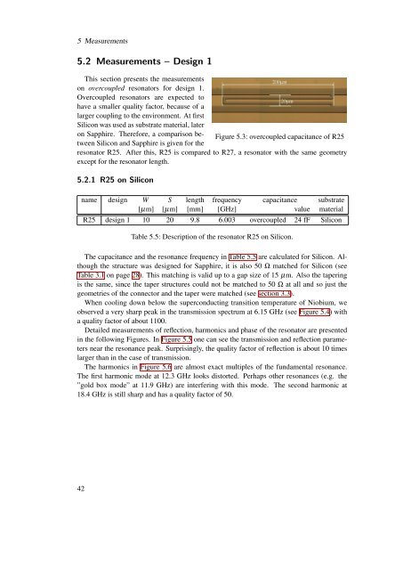
5 Measurements5.2 Measurements – <strong>Design</strong> 1This section presents the measurementson overcoupled resonators for design 1.Overcoupled resonators are expected tohave a smaller quality factor, because <strong>of</strong> alarger coupling to the environment. At firstSilicon was used as substrate material, lateron Sapphire. Therefore, a comparison betweenSilicon <strong>and</strong> Sapphire is given for theFigure 5.3: overcoupled capacitance <strong>of</strong> R25resonator R25. After this, R25 is compared to R27, a resonator with the same geometryexcept for the resonator length.5.2.1 R25 on Siliconname design W S length frequency capacitance substrate[µm] [µm] [mm] [GHz] value materialR25 design 1 10 20 9.8 6.003 overcoupled 24 fF SiliconTable 5.5: Description <strong>of</strong> the resonator R25 on Silicon.The capacitance <strong>and</strong> the resonance frequency in Table 5.5 are calculated for Silicon. Althoughthe structure was designed for Sapphire, it is also 50 Ω matched for Silicon (seeTable 3.1 on page 28). This matching is valid up to a gap size <strong>of</strong> 15 µm. Also the taperingis the same, since the taper structures could not be matched to 50 Ω at all <strong>and</strong> so just thegeometries <strong>of</strong> the connector <strong>and</strong> the taper were matched (see section 3.3).When cooling down below the superconducting transition temperature <strong>of</strong> Niobium, weobserved a very sharp peak in the transmission spectrum at 6.15 GHz (see Figure 5.4) witha quality factor <strong>of</strong> about 1100.Detailed measurements <strong>of</strong> reflection, harmonics <strong>and</strong> phase <strong>of</strong> the resonator are presentedin the following Figures. In Figure 5.5 one can see the transmission <strong>and</strong> reflection parametersnear the resonance peak. Surprisingly, the quality factor <strong>of</strong> reflection is about 10 timeslarger than in the case <strong>of</strong> transmission.The harmonics in Figure 5.6 are almost exact multiples <strong>of</strong> the fundamental resonance.The first harmonic mode at 12.3 GHz looks distorted. Perhaps other resonances (e.g. the”gold box mode” at 11.9 GHz) are interfering with this mode. The second harmonic at18.4 GHz is still sharp <strong>and</strong> has a quality factor <strong>of</strong> 50.42