SD Specifications Part 1 UHS-II Simplified Addendum - SD Association
SD Specifications Part 1 UHS-II Simplified Addendum - SD Association
SD Specifications Part 1 UHS-II Simplified Addendum - SD Association

Create successful ePaper yourself
Turn your PDF publications into a flip-book with our unique Google optimized e-Paper software.
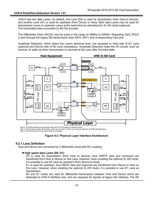
<strong>UHS</strong>-<strong>II</strong> <strong>Simplified</strong> <strong>Addendum</strong> Version 1.01©Copyright 2010-2013 <strong>SD</strong> Card <strong>Association</strong><strong>UHS</strong>-<strong>II</strong> has two data Lanes. As default, one Lane (D0) is used for downstream (from Host to Device),and another Lane (D1) is used for upstream (from Device to Host). Both data Lanes may be used fordownstream Lanes or upstream Lanes at the same time by activating the 2L-HD mode (optional).The transmitted data is encoded by 8b/10b encoder.The Differential Clock (RCLK) may be tuned in the range of 26MHz to 52MHz. Regarding Card, RCLKis sent through the legacy <strong>SD</strong> transmission lines DAT0, DAT1 and corresponding Card pins.Amplitude Detectors, which detect the Lane's electrical level, are equipped to Host side of D1 Lane(optional) and Device side of D0 Lane (mandatory). Amplitude Detectors make the I/O circuits, such asreceiver, to wake up when transmission is resumed at the Lane after Dormant state.Host Equipment<strong>UHS</strong>-<strong>II</strong> <strong>SD</strong> CardLegacy PinsOSCRef.CLKRCLKLegacy I/FRCLKDAT0/RCLK+Legacy I/FRCLKDAT1/RCLK-Legacy I/FLegacy I/FPCLK8/168/168b/10b10b/8bPLLSER/DESTxD0Additional Signal PinsD0+D0-TxPLLSER/DES10b/8b8b/10bPCLK8/168/16Link LayerCTRLSTATUS8/168/16PHY Logic10b/8b8b/10bSER/DESRxTxRxD1D1+D1-AmplitudeDetectorRxTxRxSER/DESPHY Logic8b/10b10b/8bCTRLSTATUS8/168/16Link LayerAmplitudeDetectorPhysical LayerNote 1: All function blocks and connection lines used in 2L-HD mode are colored by gray.Note 2: I/O circuits of Legacy <strong>SD</strong> Interface, which are not used in <strong>UHS</strong>-<strong>II</strong>, are shown by dash-line and filled with light gray.Note 3: RCLK termination of each device shall be switchable.Figure 4-2: Physical Layer Interface Architecture4.2.1 Lane DefinitionHost and Device are connected by 3 differential Lanes with DC coupling:• High speed data Lanes (D0, D1):D0 is used for downstream (from Host to Device), thus WRITE data and command aretransferred from Host to Device on this Lane. However, when enabling the optional 2L-HD mode,it is possible to use D0 Lane as upstream (from Device to Host).D1 is used for upstream, thus READ data and response are transferred from Device to Host onthis Lane. However, when enabling the optional 2L-HD mode, it is possible to use D1 Lane asdownstream.D0 and D1 Lanes are used for differential transmission between Host and Device which arededicated to <strong>UHS</strong>-<strong>II</strong> interface only, and are separate for signals of legacy <strong>SD</strong> interface. The D015