- Page 2 and 3:
ITEM TOOLKIT ® TUTORIAL GETTING ST
- Page 4 and 5:
Contents Contents i CONTENTS ......
- Page 6 and 7:
Contents 1. CREATING A BILL OF MATE
- Page 8 and 9:
Preface 1 Preface ITEM ToolKit is a
- Page 10 and 11:
Chapter 1 Introducing ITEM ToolKit
- Page 12 and 13:
Chapter 1 Introducing ITEM ToolKit
- Page 14 and 15:
2. Hardware and Software Requiremen
- Page 16 and 17:
Chapter 2 Installing ITEM ToolKit 9
- Page 18 and 19:
Chapter 2 Installing ITEM ToolKit 1
- Page 20 and 21:
Chapter 2 Installing ITEM ToolKit 1
- Page 22 and 23:
Chapter 2 Installing ITEM ToolKit 1
- Page 24 and 25:
Activating the Software Chapter 2 I
- Page 26 and 27:
Chapter 2 Installing ITEM ToolKit 1
- Page 28 and 29:
Chapter 2 Installing ITEM ToolKit 2
- Page 30 and 31:
Chapter 2 Installing ITEM ToolKit 2
- Page 32 and 33:
Chapter 2 Installing ITEM ToolKit 2
- Page 34 and 35:
Chapter 2 Installing ITEM ToolKit 2
- Page 36 and 37:
• When the InstallShield Wizard C
- Page 38 and 39:
Chapter 2 Installing ITEM ToolKit 3
- Page 40 and 41:
Chapter 2 Installing ITEM ToolKit 3
- Page 42 and 43:
Chapter 2 Installing ITEM ToolKit 3
- Page 44 and 45:
Network TCP/IP Connections Setup Ch
- Page 46 and 47:
3. License Server Installation Chap
- Page 48 and 49:
Installing the License Manager Chap
- Page 50 and 51:
Chapter 2 Installing ITEM ToolKit 4
- Page 52 and 53:
Chapter 2 Installing ITEM ToolKit 4
- Page 54 and 55:
• When the InstallShield Wizard C
- Page 56 and 57:
• Selecting Unlock Online opens t
- Page 58 and 59:
Chapter 2 Installing ITEM ToolKit 5
- Page 60 and 61:
Network File Share Connections Setu
- Page 62 and 63:
Network TCP/IP Connections Setup Ch
- Page 64 and 65:
4. Network Client Installation Chap
- Page 66 and 67:
Installing the Software Chapter 2 I
- Page 68 and 69:
Chapter 2 Installing ITEM ToolKit 6
- Page 70 and 71:
Chapter 2 Installing ITEM ToolKit 6
- Page 72 and 73:
Chapter 2 Installing ITEM ToolKit 6
- Page 74 and 75:
Activating the Software Chapter 2 I
- Page 76 and 77:
Chapter 2 Installing ITEM ToolKit 6
- Page 78 and 79:
Chapter 2 Installing ITEM ToolKit 7
- Page 80 and 81:
5. View-Only Client Installation Ch
- Page 82 and 83:
Installing the Software Chapter 2 I
- Page 84 and 85:
Chapter 2 Installing ITEM ToolKit 7
- Page 86 and 87:
• The Choose Network Destination
- Page 88 and 89:
Chapter 2 Installing ITEM ToolKit 8
- Page 90 and 91:
Chapter 3 ToolKit Basics 83 CHAPTER
- Page 92 and 93:
Chapter 3 ToolKit Basics 85 The Sys
- Page 94 and 95:
Chapter 3 ToolKit Basics 87 The Gri
- Page 96 and 97:
Chapter 3 ToolKit Basics 89 The Cha
- Page 98 and 99:
3. The ToolKit Menus Chapter 3 Tool
- Page 100 and 101:
Add Menu Chapter 3 ToolKit Basics 9
- Page 102 and 103:
Analysis Menu Chapter 3 ToolKit Bas
- Page 104 and 105:
4. The ToolKit Toolbars Chapter 3 T
- Page 106 and 107:
Chapter 4 Project Basics 99 CHAPTER
- Page 108 and 109:
2. Opening a Project Chapter 4 Proj
- Page 110 and 111:
4. Editing Project and System Prope
- Page 112 and 113:
6. Closing a Project Chapter 4 Proj
- Page 114 and 115:
Chapter 5 Predictions 107 CHAPTER 5
- Page 116 and 117:
3. Creating a Prediction Project Ch
- Page 118 and 119:
Chapter 5 Predictions 111 F E The t
- Page 120 and 121:
Field Part Number Name Circuit Ref
- Page 122 and 123:
Chapter 5 Predictions 115 D B A C E
- Page 124 and 125:
Chapter 5 Predictions 117 Viewing R
- Page 126 and 127:
Chapter 5 Predictions 119 4. Derati
- Page 128 and 129:
2. Select the desired Derating stan
- Page 130 and 131:
Chapter 5 Predictions 123 Creating
- Page 132 and 133:
Chapter 5 Predictions 125 5. Predic
- Page 134 and 135:
The Project Toolbar The Project Too
- Page 136 and 137:
Chapter 5 Predictions 129 The NSWC
- Page 138 and 139:
Chapter 6 FMECA 131 CHAPTER 6 FMECA
- Page 140 and 141: 3. Creating a FMECA Project Chapter
- Page 142 and 143: Chapter 6 FMECA 135 A B C 2. Select
- Page 144 and 145: Chapter 6 FMECA 137 Field Mode - Re
- Page 146 and 147: Chapter 6 FMECA 139 2. Place the bl
- Page 148 and 149: Adding and Editing Components Chapt
- Page 150 and 151: Chapter 6 FMECA 143 Field Descripti
- Page 152 and 153: Defining FMECA Severity Chapter 6 F
- Page 154 and 155: 3. Click the Mode + button to add a
- Page 156 and 157: Chapter 6 FMECA 149 D F G E H J 4.
- Page 158 and 159: Chapter 6 FMECA 151 5. If no errors
- Page 160 and 161: Chapter 6 FMECA 153 Use the SEV, OC
- Page 162 and 163: Chapter 6 FMECA 155 The FMECA Dialo
- Page 164 and 165: Chapter 7 RBD 157 CHAPTER 7 RBD A r
- Page 166 and 167: 3. Creating an RBD Project Creating
- Page 168 and 169: 5. Select the Add menu from the men
- Page 170 and 171: Chapter 7 RBD 163 What is a Node? N
- Page 172 and 173: Chapter 7 RBD 165 2. Select the fai
- Page 174 and 175: When verifying RBD projects, ToolKi
- Page 176 and 177: Understanding Analysis Results Chap
- Page 178 and 179: The Default Toolbar Chapter 7 RBD 1
- Page 180 and 181: Chapter 7 RBD 173 The Project Toolb
- Page 182 and 183: Chapter 7 RBD 175 The Graph Toolbar
- Page 184 and 185: Chapter 8 Fault Tree 177 CHAPTER 8
- Page 186 and 187: Chapter 8 Fault Tree 179 Furthermor
- Page 188 and 189: Chapter 8 Fault Tree 181 Field Desc
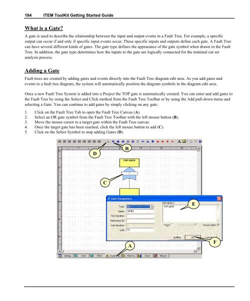
- Page 192 and 193: 6. Right Mouse Click on the new Gat
- Page 194 and 195: Chapter 8 Fault Tree 187 • Dorman
- Page 196 and 197: 2. If no errors are detected the fo
- Page 198 and 199: Understanding Analysis Results Chap
- Page 200 and 201: Chapter 8 Fault Tree 193 3. Select
- Page 202 and 203: Chapter 8 Fault Tree 195 4. Fault T
- Page 204 and 205: The Project Toolbar The Project Too
- Page 206 and 207: The Align Toolbar Chapter 8 Fault T
- Page 208 and 209: Chapter 8 Fault Tree 201 The Canvas
- Page 210 and 211: Chapter 9 Markov 203 CHAPTER 9 Mark
- Page 212 and 213: 2. ITEM ToolKit & Markov Analysis C
- Page 214 and 215: Chapter 9 Markov 207 Field Title Na
- Page 216 and 217: Chapter 9 Markov 209 11. The next s
- Page 218 and 219: S 5 Primary Repaired X Chapter 9 Ma
- Page 220 and 221: Chapter 9 Markov 213 any number of
- Page 222 and 223: Understanding Analysis Results Chap
- Page 224 and 225: Chapter 9 Markov 217 3. The Markov
- Page 226 and 227: The Default Toolbar Chapter 9 Marko
- Page 228 and 229: The Canvas Toolbar The Canvas Toolb
- Page 230 and 231: The Graph Toolbar Chapter 9 Markov
- Page 232 and 233: Chapter 10 MainTain 225 CHAPTER 10
- Page 234 and 235: 3. Creating a Maintain Project Chap
- Page 236 and 237: Chapter 10 MainTain 229 8. In the S
- Page 238 and 239: Chapter 10 MainTain 231 Defining th
- Page 240 and 241:
Viewing Results To view the project
- Page 242 and 243:
Chapter 10 MainTain 235 4. Maintain
- Page 244 and 245:
The Project Toolbar The Project Too
- Page 246 and 247:
Chapter 11 SpareCost 239 CHAPTER 11
- Page 248 and 249:
Powerful Customizable Reports ToolK
- Page 250 and 251:
Chapter 11 SpareCost 243 The follow
- Page 252 and 253:
Chapter 11 SpareCost 245 F B D A C
- Page 254 and 255:
Chapter 11 SpareCost 247 23. Enter
- Page 256 and 257:
Understanding Analysis Results The
- Page 258 and 259:
Chapter 11 SpareCost 251 The Defaul
- Page 260 and 261:
Shortcut Keys: Chapter 11 SpareCost
- Page 262 and 263:
Chapter 12 Event Tree 255 CHAPTER 1
- Page 264 and 265:
Chapter 12 Event Tree 257 Once the
- Page 266 and 267:
Binary Decision Diagram (BDD): Chap
- Page 268 and 269:
5. Enter your project information b
- Page 270 and 271:
Chapter 12 Event Tree 263 11. Enter
- Page 272 and 273:
5. Click on Event List and the Proj
- Page 274 and 275:
2. Double Click on the Consequence
- Page 276 and 277:
1. Click on the Event Tree Tab to o
- Page 278 and 279:
Chapter 12 Event Tree 271 To Verify
- Page 280 and 281:
Chapter 12 Event Tree 273 Importanc
- Page 282 and 283:
Chapter 12 Event Tree 275 4. Event
- Page 284 and 285:
The Project Toolbar The Project Too
- Page 286 and 287:
Chapter 12 Event Tree 279 The Zoom
- Page 288 and 289:
Chapter 13 Reports 281 CHAPTER 13 W
- Page 290 and 291:
Chapter 13 Reports 283 Preview Tab
- Page 292 and 293:
Chapter 13 Reports 285 This is an e
- Page 294 and 295:
Chapter 13 Reports 287 Inserting a
- Page 296 and 297:
Chapter 13 Reports 289 The Field Wi
- Page 298 and 299:
Chapter 13 Reports 291 4. Problem S
- Page 300 and 301:
Chapter 14 Import/Export 293 CHAPTE
- Page 302 and 303:
Chapter 14 Import/Export 295 2. Imp
- Page 304 and 305:
Chapter 14 Import/Export 297 8. Cli
- Page 306 and 307:
Chapter 14 Import/Export 299 3. Exp
- Page 308 and 309:
Chapter 14 Import/Export 301 Select
- Page 310 and 311:
Chapter 15 Library Facilities 303 C
- Page 312 and 313:
Chapter 15 Library Facilities 305 2
- Page 314 and 315:
Chapter 15 Library Facilities 307 3
- Page 316 and 317:
Chapter 16 Grid View Customization
- Page 318 and 319:
Chapter 16 Grid View Customization
- Page 320:
ITEM Software (USA) 34 Executive Pa