Getting Started with InfoSphere Data Architect

Create successful ePaper yourself
Turn your PDF publications into a flip-book with our unique Google optimized e-Paper software.
Chapter 8 – Model Mapping and Discovery 151<br />
Relationships <strong>with</strong>in a mapping model are color-coded. The color codes are determined by the settings in<br />
the Preferences window, in the Mapping Editor page (found under the <strong>Data</strong> Management node).<br />
Note that the relationships you created are in blue or light blue, depending on whether the relationship is<br />
selected. Within the workbench, these are considered to be accepted mappings and are an approved part<br />
of the mapping model. Discovered mappings are in gold if they are not selected, and they appear to be<br />
brown if you select them.<br />
You select mappings to approve or reject them. If you reject a mapping, the mapping line disappears from<br />
the mapping model.<br />
First, you will approve a couple of relationships manually. Then, you will inspect the remaining<br />
relationships and determine whether to accept the mappings.<br />
To accept or reject discovered relationships:<br />
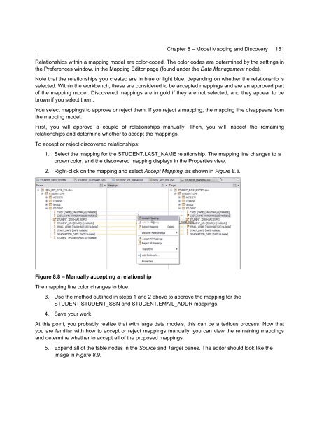
1. Select the mapping for the STUDENT.LAST_NAME relationship. The mapping line changes to a<br />
brown color, and the discovered mapping displays in the Properties view.<br />
2. Right-click on the mapping and select Accept Mapping, as shown in Figure 8.8.<br />
Figure 8.8 – Manually accepting a relationship<br />
The mapping line color changes to blue.<br />
3. Use the method outlined in steps 1 and 2 above to approve the mapping for the<br />
STUDENT.STUDENT_SSN and STUDENT.EMAIL_ADDR mappings.<br />
4. Save your work.<br />
At this point, you probably realize that <strong>with</strong> large data models, this can be a tedious process. Now that<br />
you are familiar <strong>with</strong> how to accept or reject mappings manually, you can view the remaining mappings<br />
and determine whether to accept all of the proposed mappings.<br />
5. Expand all of the table nodes in the Source and Target panes. The editor should look like the<br />
image in Figure 8.9.