- Page 1 and 2:
HP EliteBook 2530p Notebook PC Main
- Page 3 and 4:
Safety warning notice WARNING! To r
- Page 5 and 6:
Table of contents 1 Product descrip
- Page 7 and 8:
6 Specifications ..................
- Page 9 and 10:
1 Product description Category Prod
- Page 11 and 12:
Category Description S4/S5 wake on
- Page 13 and 14:
2 External component identification
- Page 15 and 16:
Component Description (7) Battery l
- Page 17 and 18:
Component Description (5) Presentat
- Page 19 and 20:
Display Component Description (1) A
- Page 21 and 22:
Rear components Component Descripti
- Page 23 and 24:
Left-side components NOTE: Refer to
- Page 25 and 26:
Component Description (8) Speaker P
- Page 27 and 28:
3 Illustrated parts catalog Serial
- Page 29 and 30:
Computer major components Item Desc
- Page 31 and 32:
Item Description Spare part number
- Page 33 and 34:
Item Description Spare part number
- Page 35 and 36:
Display components Item Description
- Page 37 and 38:
Mass storage Item Description Spare
- Page 39 and 40:
Plastics Kit Item Description Spare
- Page 41 and 42:
Sequential part number listing Spar
- Page 43 and 44:
Spare part number Description 49256
- Page 45 and 46:
4 Removal and replacement procedure
- Page 47 and 48:
Grounding guidelines Electrostatic
- Page 49 and 50:
Equipment guidelines Grounding equi
- Page 51 and 52:
Component replacement procedures Th
- Page 53 and 54:
Computer feet The computer feet are
- Page 55 and 56:
SIM NOTE: This section applies only
- Page 57 and 58:
5. Remove the Bluetooth module (3).
- Page 59 and 60:
4. Remove the memory module (2) by
- Page 61 and 62:
Description Spare part number ●
- Page 63 and 64:
Primary hard drive NOTE: The 4.57-c
- Page 65 and 66:
9. Pull the edges of the protective
- Page 67 and 68:
5. Remove the two Phillips PM2.0×4
- Page 69 and 70:
7. Remove the optical drive bracket
- Page 71 and 72:
Before removing the switch cover an
- Page 73 and 74:
9. Release the ZIF connector (3) to
- Page 75 and 76:
Secondary hard drive NOTE: The 6.35
- Page 77 and 78:
6. Remove the secondary hard drive
- Page 79 and 80: 14. Remove the secondary hard drive
- Page 81 and 82: Display assembly Description Spare
- Page 83 and 84: 7. Remove the two Mylar screw cover
- Page 85 and 86: 17. Remove the display panel (3). 1
- Page 87 and 88: Top cover Description Spare part nu
- Page 89 and 90: 6. Lift the rear edge of the top co
- Page 91 and 92: 3. Release the LED board (3) from t
- Page 93 and 94: Bluetooth module cable NOTE: The Bl
- Page 95 and 96: Remove the system board: 1. Release
- Page 97 and 98: 3. Turn the system board rightside
- Page 99 and 100: 4. Remove the modem module . Revers
- Page 101 and 102: 4. Lift the fan up (3) to remove. R
- Page 103 and 104: 3. Remove the heat sink (2). NOTE:
- Page 105 and 106: Using Computer Setup Navigating and
- Page 107 and 108: Computer Setup menus File menu The
- Page 109 and 110: Diagnostics menu Select To do this
- Page 111 and 112: Select To do this NOTE: Availabilit
- Page 113 and 114: 6 Specifications Computer specifica
- Page 115 and 116: Hard drive specifications 250-GB* 2
- Page 117 and 118: DVD±RW and CD-RW SuperMulti Double
- Page 119 and 120: System interrupt specifications Har
- Page 121 and 122: I/O address (hex) System function (
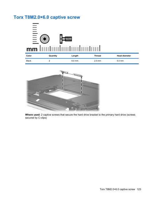
- Page 123 and 124: 7 Screw listing This section provid
- Page 125 and 126: Where used: 2 screws that secure th
- Page 127 and 128: Where used: One screw that secures
- Page 129: Where used: 4 screws that connect t
- Page 133 and 134: Phillips PM2.5×6.0 captive screw C
- Page 135 and 136: Where used: 4 screws that secure th
- Page 137 and 138: Where used: 3 screws that secure th
- Page 139 and 140: Phillips PM2.5×11.0 captive screw
- Page 141 and 142: Backing up your information Recover
- Page 143 and 144: Using f11 CAUTION: Using f11 comple
- Page 145 and 146: Backing up your information Recover
- Page 147 and 148: 9 Connector pin assignments Audio-i
- Page 149 and 150: External monitor Pin Signal 1 Red a
- Page 151 and 152: RJ-11 (modem) Pin Signal 1 Unused 2
- Page 153 and 154: Universal Serial Bus Pin Signal 1 +
- Page 155 and 156: Requirements for specific countries
- Page 157 and 158: Display WARNING! The backlight cont
- Page 159 and 160: 4. Disconnect all display panel cab
- Page 161 and 162: 15. Remove the backlight cables (1)
- Page 163 and 164: Index Symbols/Numerics 1394 port, i
- Page 165 and 166: keyboard light button, identifying
- Page 167: system date and time 99 System Diag