display

You also want an ePaper? Increase the reach of your titles
YUMPU automatically turns print PDFs into web optimized ePapers that Google loves.
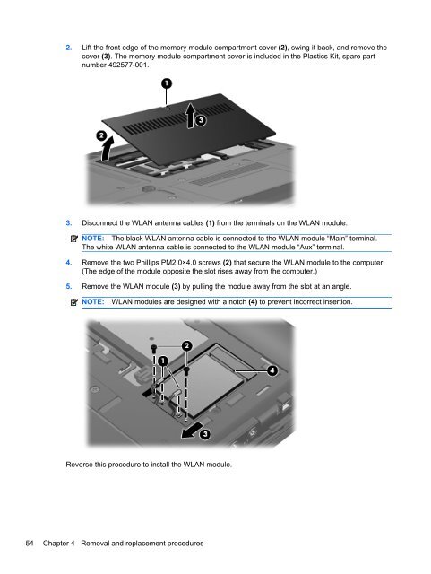
2. Lift the front edge of the memory module compartment cover (2), swing it back, and remove the<br />
cover (3). The memory module compartment cover is included in the Plastics Kit, spare part<br />
number 492577-001.<br />
3. Disconnect the WLAN antenna cables (1) from the terminals on the WLAN module.<br />
NOTE: The black WLAN antenna cable is connected to the WLAN module “Main” terminal.<br />
The white WLAN antenna cable is connected to the WLAN module “Aux” terminal.<br />
4. Remove the two Phillips PM2.0×4.0 screws (2) that secure the WLAN module to the computer.<br />
(The edge of the module opposite the slot rises away from the computer.)<br />
5. Remove the WLAN module (3) by pulling the module away from the slot at an angle.<br />
NOTE:<br />
WLAN modules are designed with a notch (4) to prevent incorrect insertion.<br />
Reverse this procedure to install the WLAN module.<br />
54 Chapter 4 Removal and replacement procedures