1 2 3 4 5
1 2 3 4 5
1 2 3 4 5

Create successful ePaper yourself
Turn your PDF publications into a flip-book with our unique Google optimized e-Paper software.
1<br />
12<br />
3<br />
4<br />
5<br />
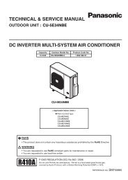
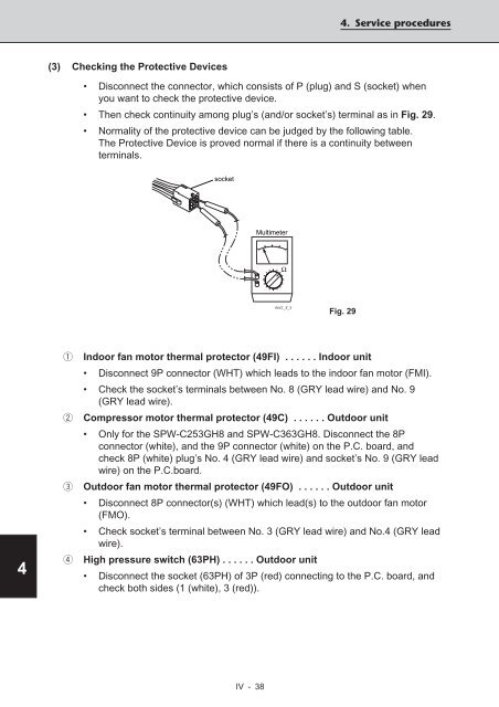
(3) Checking the Protective Devices<br />
IV - 38<br />
4. Service procedures<br />
• Disconnect the connector, which consists of P (plug) and S (socket) when<br />
you want to check the protective device.<br />
• Then check continuity among plug’s (and/or socket’s) terminal as in Fig. 29.<br />
• Normality of the protective device can be judged by the following table.<br />
The Protective Device is proved normal if there is a continuity between<br />
terminals.<br />
socket<br />
Multimeter<br />
Fig. 29<br />
1 Indoor fan motor thermal protector (49FI) . . . . . . Indoor unit<br />
• Disconnect 9P connector (WHT) which leads to the indoor fan motor (FMI).<br />
• Check the socket’s terminals between No. 8 (GRY lead wire) and No. 9<br />
(GRY lead wire).<br />
2 Compressor motor thermal protector (49C) . . . . . . Outdoor unit<br />
• Only for the SPW-C253GH8 and SPW-C363GH8. Disconnect the 8P<br />
connector (white), and the 9P connector (white) on the P.C. board, and<br />
check 8P (white) plug’s No. 4 (GRY lead wire) and socket’s No. 9 (GRY lead<br />
wire) on the P.C.board.<br />
3 Outdoor fan motor thermal protector (49FO) . . . . . . Outdoor unit<br />
• Disconnect 8P connector(s) (WHT) which lead(s) to the outdoor fan motor<br />
(FMO).<br />
• Check socket’s terminal between No. 3 (GRY lead wire) and No.4 (GRY lead<br />
wire).<br />
4 High pressure switch (63PH) . . . . . . Outdoor unit<br />
• Disconnect the socket (63PH) of 3P (red) connecting to the P.C. board, and<br />
check both sides (1 (white), 3 (red)).<br />
Ω<br />
0642_X_S