1 2 3 4 5
1 2 3 4 5
1 2 3 4 5

Create successful ePaper yourself
Turn your PDF publications into a flip-book with our unique Google optimized e-Paper software.
(4) Checking the Electrical Parts<br />
IV - 39<br />
4. Service procedures<br />
1 Power transformer (TR1) ................. Indoor unit *Measure the coil resistance.<br />
• Primary ; Measure the resistance between No.1 and No.3<br />
(WHT lead wires) terminals of 3P (WHT) socket<br />
connected to power transformer.<br />
• Secondary 14V ; Measure the resistance between No.1 and No.2<br />
(RED lead wires).<br />
10V ; Measure the resistance between No.3 and No.4<br />
(BRN lead wires).<br />
Refer to “1-3 Other component specifications”.<br />
2 Power transformer (TR) ............ Outdoor unit *Measure the coil resistance.<br />
• Primary ; Measure the resistance between No.1 and No.3<br />
(WHT lead wires) terminals of 3P(WHT) socket jointed<br />
to power transformer.<br />
• Secondary 14 V ; Measure the resistance between No.1 and No.2<br />
(BRN lead wires).<br />
Refer to “1-3 Other component specifications”.<br />
3 Indoor fan motor (FMI) ............... Indoor unit *Measure the coil resistance.<br />
• Measure the resistance between each terminal of 9P (WHT) socket<br />
connected to the indoor fan motor.<br />
Refer to “1–2–(A) Major component specifications”.<br />
4 Outdoor fan motor (FMO) ........... Outdoor unit *Measure the coil resistance.<br />
• Measure the resistance in the same manner as explained above 3.<br />
Refer to “1–2–(B)Major component specifications”.<br />
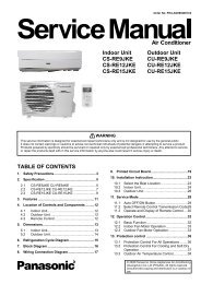
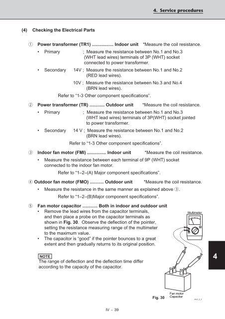
5 Fan motor capacitor ............ Both in indoor and outdoor unit<br />
• Remove the lead wires from the capacitor terminals,<br />
and then place a probe on the capacitor terminals as<br />
shown in Fig. 30. Observe the deflection of the pointer,<br />
setting the resistance measuring range of the multimeter<br />
to the maximum value.<br />
• The capacitor is “good” if the pointer bounces to a great<br />
extent and then gradually returns to its original position.<br />
NOTE<br />
The range of deflection and the deflection time differ<br />
according to the capacity of the capacitor.<br />
Fig. 30<br />
Fan motor<br />
Capacitor<br />
Multimeter<br />
0643_X_S<br />
1<br />
2<br />
3<br />
4<br />
5