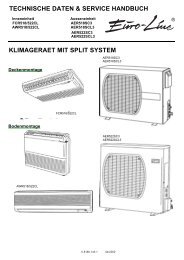
- Page 1 and 2:
TECHNICAL DATA & SERVICE MANUAL ASR
- Page 3 and 4:
WHO SHOULD USE THIS MANUAL This ser
- Page 5 and 6:
Introduction: Read Me First! This m
- Page 7 and 8:
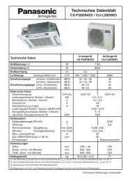
1 12 3 4 5 1-1 Unit Specifications
- Page 9 and 10:
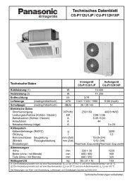
1 12 3 4 5 1-1 Unit Specifications
- Page 11 and 12:
1 12 3 4 5 1-1 Unit Specifications
- Page 13 and 14:
1 12 3 4 5 1-1 Unit Specifications
- Page 15 and 16:
1 12 3 4 5 1-1 Unit Specifications
- Page 17 and 18:
1 12 3 4 5 1-1 Unit Specifications
- Page 19 and 20:
1 12 3 4 5 1-1 Unit Specifications
- Page 21 and 22:
1 12 3 4 5 1-1 Unit Specifications
- Page 23 and 24:
1 12 3 4 5 1-1 Unit Specifications
- Page 25 and 26:
1 12 3 4 5 1-1 Unit Specifications
- Page 27 and 28:
1 12 3 4 5 1-1 Unit Specifications
- Page 29 and 30:
1 12 3 4 5 1-1 Unit Specifications
- Page 31 and 32:
1 12 3 4 5 1-2 Major Component Spec
- Page 33 and 34:
1 12 3 4 5 1-2 Major Component Spec
- Page 35 and 36:
1 12 3 4 5 1-2 Major Component Spec
- Page 37 and 38:
1-2 Major Component Specifications
- Page 39 and 40:
1-2 Major Component Specifications
- Page 41 and 42:
1-2 Major Component Specifications
- Page 43 and 44:
1-2 Major Component Specifications
- Page 45 and 46:
1-2 Major Component Specifications
- Page 47 and 48:
1-3 Other Component Specifications
- Page 49 and 50:
1 12 3 4 5 1-3 Other Component Spec
- Page 51 and 52:
1 12 3 4 5 1-3 Other Component Spec
- Page 53 and 54:
1 12 3 4 5 1-4 Dimensional Data (A)
- Page 55 and 56:
1 12 3 4 5 1-4 Dimensional Data (A)
- Page 57 and 58:
1 12 3 4 5 1-4 Dimensional Data 11
- Page 59 and 60:
1-4 Dimensional Data 340 735 (B) Ou
- Page 61 and 62:
1-5 Refrigerant Flow Diagram Outdoo
- Page 63 and 64:
1-5 Refrigerant Flow Diagram Outdoo
- Page 65 and 66:
1-7 Cooling Capacity Indoor Unit :
- Page 67 and 68:
1-7 Cooling Capacity Indoor Unit :
- Page 69 and 70:
1-7 Cooling Capacity Indoor Unit :
- Page 71 and 72:
1-7 Cooling Capacity Indoor Unit :
- Page 73 and 74:
1-7 Cooling Capacity Indoor Unit :
- Page 75 and 76:
1-7 Cooling Capacity Indoor Unit :
- Page 77 and 78:
● Heating Capacity NOTE Comp. mot
- Page 79 and 80:
OCTAVE BAND SOUND PRESSURE LEVEL, d
- Page 81 and 82:
1 12 3 4 5 1-8 Noise Criterion Curv
- Page 83 and 84:
1-10 Air throw Distance Chart 4-Way
- Page 85 and 86:
1-11 Installation Instructions Tubi
- Page 87 and 88:
1-11 Installation Instructions Outd
- Page 89 and 90:
1-11 Installation Instructions Sele
- Page 91 and 92:
1-11 Installation Instructions ■
- Page 93 and 94:
1-11 Installation Instructions ■
- Page 95 and 96:
1-11 Installation Instructions Elec
- Page 97 and 98:
1-11 Installation Instructions Elec
- Page 99 and 100:
1-11 Installation Instructions Elec
- Page 101 and 102:
1-11 Installation Instructions Elec
- Page 103 and 104:
1-11 Installation Instructions Elec
- Page 105 and 106:
2. Processes and functions 2. PROCE
- Page 107 and 108:
(B) Heating REMOTE CONTROL SENSOR (
- Page 109 and 110:
2-3 Automatic Fan Speed (Indoor Uni
- Page 111 and 112:
2-5 Freeze Prevention (Cooling) 2.
- Page 113 and 114:
2-7 Overload Protection (Heating) T
- Page 115 and 116:
2-9 Auto. Mode for Automatic Heatin
- Page 117 and 118:
2-11 4-Way Valve, Solenoid Control
- Page 119 and 120:
2-13 Electronic Expansion Valve II
- Page 121 and 122:
2-16 Dehumidifying Operation II - 1
- Page 123 and 124:
2-18 Controlled by Electronic Expan
- Page 125 and 126:
3. ELECTRICAL DATA 3. Electrical da
- Page 127 and 128:
3-1 Indoor Units 1 4-Way Air Discha
- Page 129 and 130:
3-1 Indoor Units 2 Ceiling Mounted
- Page 131 and 132:
3-1 Indoor Units 6 Concealed Duct T
- Page 133 and 134:
3-2 Outdoor Units 1 AER 425 SCLE -
- Page 135 and 136:
3-2 Outdoor Units 2 AER 425 SCL3E -
- Page 137 and 138:
3-2 Outdoor Units III - 19 3. Elect
- Page 139 and 140: 1 12 3 4 5 4-1 Troubleshooting This
- Page 141 and 142: 1 12 3 4 5 RED WHT Inter-unit power
- Page 143 and 144: 1 12 3 4 5 (B) Heating b. Heating P
- Page 145 and 146: 1 12 3 4 5 Possible causes of troub
- Page 147 and 148: 1 12 3 4 5 IV - 10 4. Service proce
- Page 149 and 150: 1 12 3 4 5 IV - 12 4. Service proce
- Page 151 and 152: 1 12 3 4 5 IV - 14 4. Service proce
- Page 153 and 154: 1 12 3 4 5 11) Symptoms: LCD on the
- Page 155 and 156: 1 12 3 4 5 15) Symptom: LCD on the
- Page 157 and 158: 1 12 3 4 5 (6) Procedures When a Sp
- Page 159 and 160: 1 12 3 4 5 IV - 22 4. Service proce
- Page 161 and 162: 1 12 3 4 5 (C) Check the sensor tem
- Page 163 and 164: 1 12 3 4 5 This picture shows the s
- Page 165 and 166: 1 12 3 4 5 (F) Execute the auto. ad
- Page 167 and 168: 1 12 3 4 5 IV - 30 4. Service proce
- Page 169 and 170: 1 12 3 4 5 ( I ) Set the indoor uni
- Page 171 and 172: 1 12 3 4 5 IV - 34 4. Service proce
- Page 173 and 174: 1 12 3 4 5 4-2 Checking the Electri
- Page 175 and 176: 1 12 3 4 5 (3) Checking the Protect
- Page 177 and 178: 1 12 3 4 5 IV - 40 4. Service proce
- Page 179 and 180: 1 12 3 4 5 (5) Sensor and Solenoid
- Page 181 and 182: 1 12 3 4 5 Indoor Unit TH2 (E1), (R
- Page 183 and 184: 1 12 3 4 5 Outdoor Units • AER 44
- Page 185 and 186: 1 12 3 4 5 (7) P.C.B. Setting IV -
- Page 187 and 188: 1 12 3 4 5 (9) Automatic Address Se
- Page 189: 1 12 3 4 5 (12) Test Run Procedure
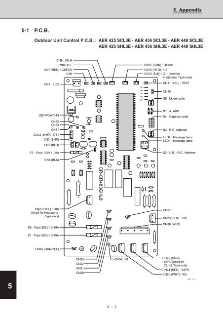
- Page 193 and 194: 1 12 3 4 5 5-1 P.C.B. Indoor Unit C