

Forgeabilité des aciers inoxydables austéno-ferritiques
Forgeabilité des aciers inoxydables austéno-ferritiques
Forgeabilité des aciers inoxydables austéno-ferritiques

Create successful ePaper yourself
Turn your PDF publications into a flip-book with our unique Google optimized e-Paper software.
tel-00672279, version 1 - 21 Feb 2012<br />
98 Chapter IV. STRAIN PARTITIONING<br />
with the deformation, which may later be observed and measured. It is possible to measure the in-<br />
plane strains at the surface of a specimen by taking images in the undeformed and in the deformed<br />
configuration, and by finding the homologous points in both configurations. Homologous points are the<br />
points in the images (undeformed and deformed) that belong to the same material point on the sam-<br />
ple. The homologous points draw a displacement field, which can be differentiated to get the in-plane<br />
strain fields. The outcome of the procedure depends strongly on the accuracy of the matching proce-<br />
dure, on the density of the homologous points, and on the range of deformations. Several techniques<br />
for defining homologous points are available. Here, it has been chosen to introduce only the two main<br />
image analysis techniques.<br />
IV.1.1 Grid techniques<br />
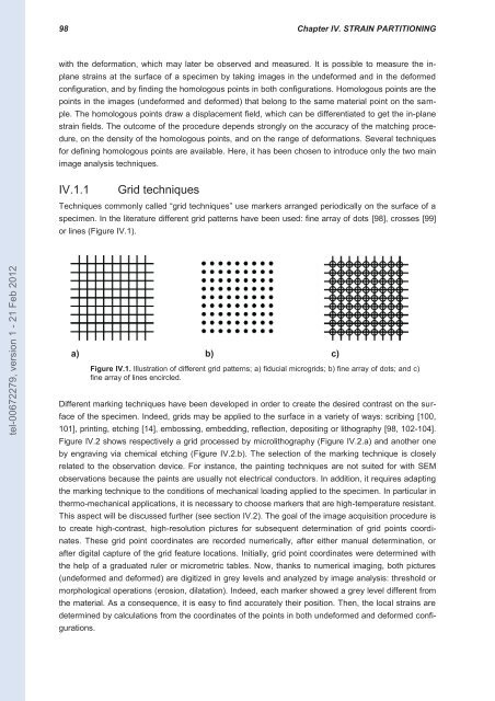
Techniques commonly called “grid techniques” use markers arranged periodically on the surface of a<br />
specimen. In the literature different grid patterns have been used: fine array of dots [98], crosses [99]<br />
or lines (Figure IV.1).<br />
a) b) c)<br />
Figure IV.1. Illustration of different grid patterns; a) fiducial microgrids; b) fine array of dots; and c)<br />
fine array of lines encircled.<br />
Different marking techniques have been developed in order to create the <strong>des</strong>ired contrast on the sur-<br />
face of the specimen. Indeed, grids may be applied to the surface in a variety of ways: scribing [100,<br />
101], printing, etching [14], embossing, embedding, reflection, depositing or lithography [98, 102-104].<br />
Figure IV.2 shows respectively a grid processed by microlithography (Figure IV.2.a) and another one<br />
by engraving via chemical etching (Figure IV.2.b). The selection of the marking technique is closely<br />
related to the observation device. For instance, the painting techniques are not suited for with SEM<br />
observations because the paints are usually not electrical conductors. In addition, it requires adapting<br />
the marking technique to the conditions of mechanical loading applied to the specimen. In particular in<br />
thermo-mechanical applications, it is necessary to choose markers that are high-temperature resistant.<br />
This aspect will be discussed further (see section IV.2). The goal of the image acquisition procedure is<br />
to create high-contrast, high-resolution pictures for subsequent determination of grid points coordi-<br />
nates. These grid point coordinates are recorded numerically, after either manual determination, or<br />
after digital capture of the grid feature locations. Initially, grid point coordinates were determined with<br />
the help of a graduated ruler or micrometric tables. Now, thanks to numerical imaging, both pictures<br />
(undeformed and deformed) are digitized in grey levels and analyzed by image analysis: threshold or<br />
morphological operations (erosion, dilatation). Indeed, each marker showed a grey level different from<br />
the material. As a consequence, it is easy to find accurately their position. Then, the local strains are<br />
determined by calculations from the coordinates of the points in both undeformed and deformed confi-<br />
gurations.


