

Forgeabilité des aciers inoxydables austéno-ferritiques
Forgeabilité des aciers inoxydables austéno-ferritiques
Forgeabilité des aciers inoxydables austéno-ferritiques

Create successful ePaper yourself
Turn your PDF publications into a flip-book with our unique Google optimized e-Paper software.
tel-00672279, version 1 - 21 Feb 2012<br />
146 Chapter IV. STRAIN PARTITIONING<br />
IV.7 Limits of the technique<br />
Technical and conceptual limitations of the microgrid technique were found during the present investi-<br />
gation, but could not be addressed due to time constraints. These different limitations of the microgrid<br />
technique are discussed in this section.<br />
IV.7.1 A time consuming technique<br />
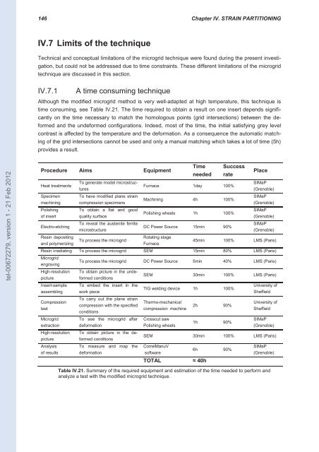
Although the modified microgrid method is very well-adapted at high temperature, this technique is<br />
time consuming, see Table IV.21. The time required to obtain a result on one insert depends signifi-<br />
cantly on the time necessary to match the homologous points (grid intersections) between the de-<br />
formed and the undeformed configurations. Indeed, most of the time, the initial satisfying grey level<br />
contrast is affected by the temperature and the deformation. As a consequence the automatic match-<br />
ing of the grid intersections cannot be used and only a manual matching which takes a lot of time (5h)<br />
provi<strong>des</strong> a result.<br />
Procedure Aims Equipment<br />
Heat treatments<br />
Specimen<br />
machining<br />
Polishing<br />
of insert<br />
Electro-etching<br />
Resin depositing<br />
and polymerizing<br />
To generate model microstruc-<br />
tures<br />
To have modified plane strain<br />
compression specimens<br />
To obtain a flat and good<br />
quality surface<br />
To reveal the austenite ferrite<br />
microstructure<br />
To process the microgrid<br />
Time<br />
needed<br />
Success<br />
rate<br />
Furnace 1day 100%<br />
Machining 4h 100%<br />
Polishing wheels 1h 100%<br />
DC Power Source 15min 90%<br />
Rotating stage<br />
Furnace<br />
Place<br />
SIMaP<br />
(Grenoble)<br />
SIMaP<br />
(Grenoble)<br />
SIMaP<br />
(Grenoble)<br />
SIMaP<br />
(Grenoble)<br />
45min 100% LMS (Paris)<br />
Resin irradiating To process the microgrid SEM 15min 80% LMS (Paris)<br />
Microgrid<br />
engraving<br />
High-resolution<br />
picture<br />
Insert-sample<br />
assembling<br />
Compression<br />
test<br />
Microgrid<br />
extraction<br />
High-resolution<br />
picture<br />
Analysis<br />
of results<br />
To process the microgrid DC Power Source 5min 40% LMS (Paris)<br />
To obtain picture in the unde-<br />
formed conditions<br />
To embed the insert in the<br />
work piece<br />
To carry out the plane strain<br />
compression with the specified<br />
conditions<br />
To see the microgrid after<br />
deformation<br />
To obtain picture in the de-<br />
formed conditions<br />
To measure and map the<br />
deformation<br />
SEM 30min 100% LMS (Paris)<br />
TIG welding device 1h 100%<br />
Thermo-mechanical<br />
compression machine<br />
Crosscut saw<br />
Polishing wheels<br />
2h 90%<br />
1h 90%<br />
University of<br />
Sheffield<br />
University of<br />
Sheffield<br />
SIMaP<br />
(Grenoble)<br />
SEM 30min 100% LMS (Paris)<br />
CorrelManuV<br />
software<br />
TOTAL ≈ 40h<br />
6h 90%<br />
SIMaP<br />
(Grenoble)<br />
Table IV.21. Summary of the required equipment and estimation of the time needed to perform and<br />
analyze a test with the modified microgrid technique.


