

Forgeabilité des aciers inoxydables austéno-ferritiques
Forgeabilité des aciers inoxydables austéno-ferritiques
Forgeabilité des aciers inoxydables austéno-ferritiques

Create successful ePaper yourself
Turn your PDF publications into a flip-book with our unique Google optimized e-Paper software.
tel-00672279, version 1 - 21 Feb 2012<br />
Chapter IV. STRAIN PARTITIONING 125<br />
� More severely strained regions<br />
Finally, it has to be noticed that the more strained zones in the microstructures are almost always si-<br />
tuated in the vicinity of the δ/γ interphase boundaries. Locally, the ratio<br />
� �<br />
� � eq<br />
eq / fluctuates between 2<br />
and 3, and in a few areas, this ratio can reach 5. These results are in agreement with the observa-<br />
tions carried out on the edge part of the hot rolled material or close to the fracture in the DENT speci-<br />
mens showing that damage always nucleates at the δ/γ interphase boundaries, see Figure I.9.b and<br />
Figure III.15.<br />
All these deformation features can be observed in the D1_W microstructure as well as in the D2_W<br />
allowing a better understanding of the mechanisms involved in the high temperature deformation of<br />
duplex stainless steels. Nevertheless, these qualitative comments do not permit to establish accurate<br />
comparisons between both gra<strong>des</strong>. Therefore, additional analysis is needed involving a more quantita-<br />
tive treatment of the strain partitioning in both microstructures.<br />
IV.5.1.2.2 Quantitative analysis<br />
Several options are available to provide quantitative results about the strain partitioning. An overview<br />
of these options is given in this section. The results are presented for each grade keeping in mind that<br />
two different regions were analyzed in the plane strain compression specimen providing two strain<br />
maps: map1 and map2.<br />
� Average deformation per phase.<br />
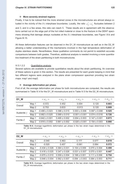
First of all, the average deformation per phase for both microstructures are computed, the results are<br />
summarized in Table IV.4 for the D1_W microstructure and in Table IV.5 for the D2_W microstructure.<br />
D1_W �� 11 � �� 22 � �� 12 � �� 33 � �� eq �<br />
Overall<br />
Austenite γ<br />
Ferrite δ<br />
Map 1 -0.572 0.452 0.004 0.120 0.603<br />
Map 2 -0.753 0.633 -0.013 0.120 0.809<br />
Map 1 -0.495 ± 0.023 0.398 ± 0.015 0.003 ± 0.006 0.097 ± 0.008 0.525<br />
Map 2 -0.662 ± 0.025 0.589 ± 0.010 -0.001 ± 0.001 0.074 ± 0.016 0.726<br />
Map 1 -0.642 ± 0.001 0.495 ± 0.002 0.004 ± 0.003 0.147 ± 0.001 0.673<br />
Map 2 -0.816 ± 0.002 0.661 ± 0.002 -0.020 ± 0.001 0.154 ± 0.003 0.866<br />
Table IV.4. Average logarithmic deformation per phase in the two strain maps determined in the<br />
D1_W microstructure.<br />
D2_W �� 11 � �� 22 � �� 12 � �� 33 � �� eq �<br />
Overall<br />
Austenite γ<br />
Ferrite δ<br />
Map 1 -0.540 0.463 0.177 0.077 0.619<br />
Map 2 -0.520 0.457 -0.061 0.064 0.572<br />
Map 1 -0.434 ± 0.028 0.364 ± 0.031 0.154 ± 0.009 0.070 ± 0.004 0.499<br />
Map 2 -0.416 ± 0.025 0.347 ± 0.026 -0.031 ± 0.007 0.070 ± 0.001 0.447<br />
Map 1 -0.670 ± 0.010 0.559 ± 0.004 0.198 ± 0.001 0.111 ± 0.006 0.754<br />
Map 2 -0.646 ± 0.004 0.562 ± 0.007 -0.094 ± 0.003 0.084 ± 0.003 0.711<br />
Table IV.5. Average logarithmic deformation per phase in the two strain maps determined in the<br />
D2_W microstructure.


