Configuration Manual Synchronous Motors 1FT6 - Siemens ...
Configuration Manual Synchronous Motors 1FT6 - Siemens ...
Configuration Manual Synchronous Motors 1FT6 - Siemens ...

Create successful ePaper yourself
Turn your PDF publications into a flip-book with our unique Google optimized e-Paper software.
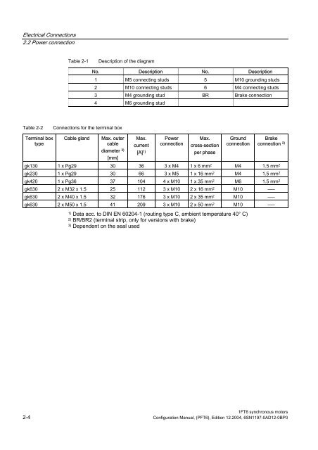
Electrical Connections<br />
2.2 Power connection<br />
Table 2-1 Description of the diagram<br />
Table 2-2 Connections for the terminal box<br />
Terminal box<br />
type<br />
No. Description No. Description<br />
Cable gland Max. outer<br />
cable<br />
1 M5 connecting studs 5 M10 grounding studs<br />
2 M10 connecting studs 6 M4 connecting studs<br />
3 M4 grounding stud BR Brake connection<br />
4 M6 grounding stud<br />
diameter 3)<br />
[mm]<br />
Max.<br />
current<br />
[A] 1)<br />
Power<br />
connection<br />
Max.<br />
cross-section<br />
per phase<br />
Ground<br />
connection<br />
Brake<br />
connection 2)<br />
gk130 1 x Pg29 30 36 3 x M4 1 x 6 mm 2 M4 1.5 mm 2<br />
gk230 1 x Pg29 30 66 3 x M5 1 x 16 mm 2 M4 1.5 mm 2<br />
gk420 1 x Pg36 37 104 4 x M10 1 x 35 mm 2 M6 1.5 mm 2<br />
gk630 2 x M32 x 1.5 25 112 3 x M10 2 x 16 mm 2 M10 –––<br />
gk630 2 x M40 x 1.5 32 176 3 x M10 2 x 35 mm 2 M10 –––<br />
gk630 2 x M50 x 1.5 41 209 3 x M10 2 x 50 mm 2 M10 –––<br />
1) Data acc. to DIN EN 60204-1 (routing type C, ambient temperature 40° C)<br />
2) BR/BR2 (terminal strip, only for versions with brake)<br />
3) Dependent on the seal used<br />
<strong>1FT6</strong> synchronous motors<br />
2-4 <strong>Configuration</strong> <strong>Manual</strong>, (PFT6), Edition 12.2004, 6SN1197-0AD12-0BP0