SPRING 2024
Distributor's Link Magazine Spring 2024 / Vol 47 No 2
Distributor's Link Magazine Spring 2024 / Vol 47 No 2

Create successful ePaper yourself
Turn your PDF publications into a flip-book with our unique Google optimized e-Paper software.
156<br />
THE DISTRIBUTOR’S LINK<br />
LAURENCE CLAUS HOW FASTENERS ARE MADE - PART 2: HOT HEADING AND SCREW MACHINING from page 126<br />
through a cutter which allows the part to fully or partially<br />
feed through the die. These threads are most likely cut<br />
threads. The other method is to use a pair of cylindrical<br />
roll dies (see Figure 6). These form the threads and can<br />
provide however many revolutions are needed to fully<br />
form the thread.<br />
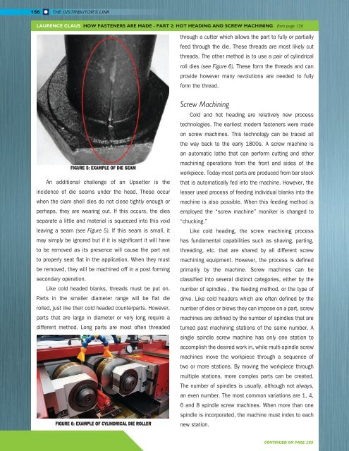
FIGURE 5: EXAMPLE OF DIE SEAM<br />
An additional challenge of an Upsetter is the<br />
incidence of die seams under the head. These occur<br />
when the clam shell dies do not close tightly enough or<br />
perhaps, they are wearing out. If this occurs, the dies<br />
separate a little and material is squeezed into this void<br />
leaving a seam (see Figure 5). If this seam is small, it<br />
may simply be ignored but if it is significant it will have<br />
to be removed as its presence will cause the part not<br />
to properly seat flat in the application. When they must<br />
be removed, they will be machined off in a post forming<br />
secondary operation.<br />
Like cold headed blanks, threads must be put on.<br />
Parts in the smaller diameter range will be flat die<br />
rolled, just like their cold headed counterparts. However,<br />
parts that are large in diameter or very long require a<br />
different method. Long parts are most often threaded<br />
FIGURE 6: EXAMPLE OF CYLINDRICAL DIE ROLLER<br />
Screw Machining<br />
Cold and hot heading are relatively new process<br />
technologies. The earliest modern fasteners were made<br />
on screw machines. This technology can be traced all<br />
the way back to the early 1800s. A screw machine is<br />
an automatic lathe that can perform cutting and other<br />
machining operations from the front and sides of the<br />
workpiece. Today most parts are produced from bar stock<br />
that is automatically fed into the machine. However, the<br />
lesser used process of feeding individual blanks into the<br />
machine is also possible. When this feeding method is<br />
employed the “screw machine” moniker is changed to<br />
“chucking.”<br />
Like cold heading, the screw machining process<br />
has fundamental capabilities such as shaving, parting,<br />
threading, etc. that are shared by all different screw<br />
machining equipment. However, the process is defined<br />
primarily by the machine. Screw machines can be<br />
classified into several distinct categories, either by the<br />
number of spindles , the feeding method, or the type of<br />
drive. Like cold headers which are often defined by the<br />
number of dies or blows they can impose on a part, screw<br />
machines are defined by the number of spindles that are<br />
turned past machining stations of the same number. A<br />
single spindle screw machine has only one station to<br />
accomplish the desired work in, while multi-spindle screw<br />
machines move the workpiece through a sequence of<br />
two or more stations. By moving the workpiece through<br />
multiple stations, more complex parts can be created.<br />
The number of spindles is usually, although not always,<br />
an even number. The most common variations are 1, 4,<br />
6 and 8 spindle screw machines. When more than one<br />
spindle is incorporated, the machine must index to each<br />
new station.<br />
CONTINUED ON PAGE 162