SPRING 2024
Distributor's Link Magazine Spring 2024 / Vol 47 No 2
Distributor's Link Magazine Spring 2024 / Vol 47 No 2

Create successful ePaper yourself
Turn your PDF publications into a flip-book with our unique Google optimized e-Paper software.
162<br />
THE DISTRIBUTOR’S LINK<br />
LAURENCE CLAUS HOW FASTENERS ARE MADE - PART 2: HOT HEADING AND SCREW MACHINING from page 156<br />
This usually means that everything associated<br />
with the part in that spindle must be able to index.<br />
As a result, bar fed, multiple spindle screw machines<br />
vaguely resemble a gatling gun as each spindle must be<br />
independently fed with bar stock that indexes in a rotary<br />
motion around the centerline of the machine (see Figure<br />
7). The feeding method also serves as a distinguishing<br />
characteristic of the process. Screw machines may feed<br />
long, continuous bars through a bar feeding mechanism<br />
or load individual blanks into a collet or jaws that rotate<br />
on the spindle. Finally, screw machines may be known<br />
by the type of drive the machine incorporates. Traditional<br />
machines are cam driven. This means that a series<br />
of cams time when the machine performs its specific<br />
functions such as moving the tools in and out of the<br />
workpiece, indexing the machine, feeding new stock<br />
into the machine, etc. In a cam driven machine, each<br />
operation must be carefully planned and precisely timed<br />
so that the entire process becomes an elegant and<br />
finely choreographed dance. Traditional and Swiss screw<br />
machines are cam driven. Most late model equipment is<br />
numerically controlled by a computer (CNC machines).<br />
The CNC controller executes a predefined program which<br />
controls the overall machine and the precise timing,<br />
placement, and movement of each tool.<br />
Although each machine works a little differently,<br />
the fundamental concept is universal. The workpiece<br />
(continuous bar or individual blank) is fixtured into<br />
a holder (usually a split collet or a set of jaws like a<br />
drill chuck) that is integral to the spindle and grasps<br />
the workpiece allowing it to spin at the speed of the<br />
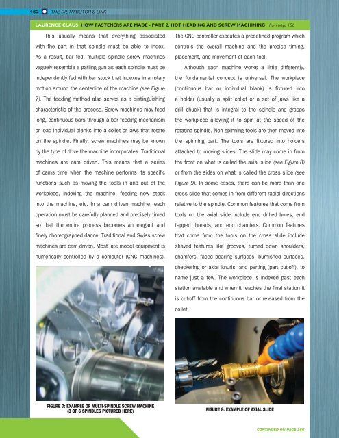
rotating spindle. Non spinning tools are then moved into<br />
the spinning part. The tools are fixtured into holders<br />
attached to moving slides. The slide may come in from<br />
the front on what is called the axial slide (see Figure 8)<br />
or from the sides on what is called the cross slide (see<br />
Figure 9). In some cases, there can be more than one<br />
cross slide that comes in from different radial directions<br />
relative to the spindle. Common features that come from<br />
tools on the axial slide include end drilled holes, end<br />
tapped threads, and end chamfers. Common features<br />
that come from the tools on the cross slide include<br />
shaved features like grooves, turned down shoulders,<br />
chamfers, faced bearing surfaces, burnished surfaces,<br />
checkering or axial knurls, and parting (part cut-off), to<br />
name just a few. The workpiece is indexed past each<br />
station available and when it reaches the final station it<br />
is cut-off from the continuous bar or released from the<br />
collet.<br />
FIGURE 7: EXAMPLE OF MULTI-SPINDLE SCREW MACHINE<br />
(3 OF 6 SPINDLES PICTURED HERE) FIGURE 8: EXAMPLE OF AXIAL SLIDE<br />
CONTINUED ON PAGE 166