APV Dryer Handbook - Umbc
APV Dryer Handbook - Umbc
APV Dryer Handbook - Umbc

Create successful ePaper yourself
Turn your PDF publications into a flip-book with our unique Google optimized e-Paper software.
50<br />
PROCESS DESCRIPTION<br />
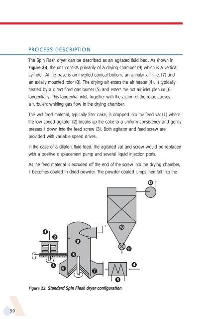
The Spin Flash dryer can be described as an agitated fluid bed. As shown in<br />
Figure 23, the unit consists primarily of a drying chamber (9) which is a vertical<br />
cylinder. At the base is an inverted conical bottom, an annular air inlet (7) and<br />
an axially mounted rotor (8). The drying air enters the air heater (4), is typically<br />
heated by a direct fired gas burner (5) and enters the hot air inlet plenum (6)<br />
tangentially. This tangential inlet, together with the action of the rotor, causes<br />
a turbulent whirling gas flow in the drying chamber.<br />
The wet feed material, typically filter cake, is dropped into the feed vat (1) where<br />
the low speed agitator (2) breaks up the cake to a uniform consistency and gently<br />
presses it down into the feed screw (3). Both agitator and feed screw are<br />
provided with variable speed drives.<br />
In the case of a dilatent fluid feed, the agitated vat and screw would be replaced<br />
with a positive displacement pump and several liquid injection ports.<br />
As the feed material is extruded off the end of the screw into the drying chamber,<br />
it becomes coated in dried powder. The powder coated lumps then fall into the<br />
1<br />
3<br />
2<br />
6<br />
8<br />
Figure 23. Standard Spin Flash dryer configuration<br />
9<br />
7<br />
5<br />
10<br />
11<br />
4<br />
12