APV Dryer Handbook - Umbc
APV Dryer Handbook - Umbc
APV Dryer Handbook - Umbc

You also want an ePaper? Increase the reach of your titles
YUMPU automatically turns print PDFs into web optimized ePapers that Google loves.
1<br />
3<br />
2<br />
6<br />
8<br />
9<br />
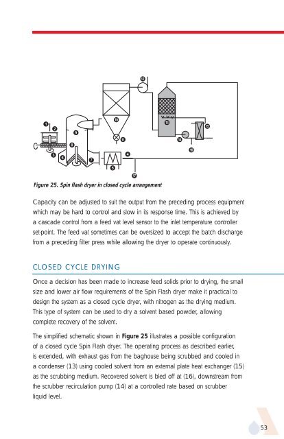
Capacity can be adjusted to suit the output from the preceding process equipment<br />
which may be hard to control and slow in its response time. This is achieved by<br />
a cascade control from a feed vat level sensor to the inlet temperature controller<br />
set-point. The feed vat sometimes can be oversized to accept the batch discharge<br />
from a preceding filter press while allowing the dryer to operate continuously.<br />
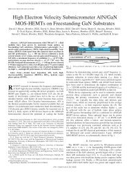
CLOSED CYCLE DRYING<br />
7<br />
Figure 25. Spin flash dryer in closed cycle arrangement<br />
5<br />
10<br />
11<br />
4<br />
17<br />
Once a decision has been made to increase feed solids prior to drying, the small<br />
size and lower air flow requirements of the Spin Flash dryer make it practical to<br />
design the system as a closed cycle dryer, with nitrogen as the drying medium.<br />
This type of system can be used to dry a solvent based powder, allowing<br />
complete recovery of the solvent.<br />
The simplified schematic shown in Figure 25 illustrates a possible configuration<br />
of a closed cycle Spin Flash dryer. The operating process as described earlier,<br />
is extended, with exhaust gas from the baghouse being scrubbed and cooled in<br />
a condenser (13) using cooled solvent from an external plate heat exchanger (15)<br />
as the scrubbing medium. Recovered solvent is bled off at (16), downstream from<br />
the scrubber recirculation pump (14) at a controlled rate based on scrubber<br />
liquid level.<br />
12<br />
13<br />
14<br />
16<br />
15<br />
53