- Page 1:
CIVIL AIR PATROL The Official Auxil
- Page 4 and 5:
ACKNOWLEDGEMENTS ACKNOWLEDGEMENTS A
- Page 7 and 8:
Chapter Chapter Chapter Chapter Cha
- Page 9 and 10:
Our ability to use air and space di
- Page 11 and 12:
glider 400 years before the first o
- Page 13 and 14:
After centuries of dreaming, flight
- Page 15 and 16:
However, hydrogen also had a seriou
- Page 17 and 18:
The first airplane pioneer in the n
- Page 19 and 20:
devotion to gliding and aviation en
- Page 21 and 22:
Langley’s last failure, two broth
- Page 23 and 24:
During the winter of 1901, they bui
- Page 25 and 26:
� kite � lighter-than-air � g
- Page 27 and 28:
Chapter Chapter Chapter Chapter Cha
- Page 29 and 30:
exceeded the speed requirements. Th
- Page 31 and 32:
Rodgers’ Vin Fiz Flyer was built
- Page 33 and 34:
Progress Progress in in Europe Euro
- Page 35 and 36:
power than one, and if one engine f
- Page 37 and 38:
Many aviation pioneers already ment
- Page 39 and 40:
in military affairs took place with
- Page 41 and 42:
FFFFFighter ighter ighter ighter ig
- Page 43 and 44:
difficulties in accepting the servi
- Page 45 and 46:
in the Wisconsin Volunteers at age
- Page 47 and 48:
SELECT THE CORRECT ANSWER 1. (Rober
- Page 49 and 50:
Chapter Chapter Chapter Chapter Cha
- Page 51 and 52:
The NC-1 came down after flying 850
- Page 53 and 54:
On November 14, 1918, 3 days after
- Page 55 and 56:
Ar Army Ar my Air Air P PPower P ow
- Page 57 and 58:
Kelly and Macready flew over Indian
- Page 59 and 60:
Early Parachute Jump Test National
- Page 61 and 62:
WWWWWomen omen omen omen’s omen
- Page 63 and 64:
On June 12, 1934, Congress passed a
- Page 65 and 66:
The engine compartment of EAA’s S
- Page 67 and 68:
The great airplane designer, Lloyd
- Page 69 and 70:
workhorse we know today. The name o
- Page 71 and 72:
Pan American’s China Clipper Mean
- Page 73 and 74:
them to respond to an Army design c
- Page 75 and 76:
qualified would be sent to designat
- Page 77 and 78:
The 332nd Fighter Group flew more t
- Page 79 and 80:
MATCHING 11. First attempt to stand
- Page 81 and 82:
Chapter Chapter Chapter Chapter Cha
- Page 83 and 84:
The Japanese built a strong Navy. T
- Page 85 and 86:
The backbone of the German Air Forc
- Page 87 and 88:
Lacking the defensive air force to
- Page 89 and 90:
The Spitfire is a prized collector
- Page 91 and 92:
86 USAAF personnel are shown here p
- Page 93 and 94:
Hitler supposedly promised Luftwaff
- Page 95 and 96:
Japanese Attack on Pearl Harbor on
- Page 97 and 98:
established within the Army Air For
- Page 99 and 100:
In fact, the lessons learned in Nor
- Page 101 and 102:
already tried daylight bombing and
- Page 103 and 104:
The P-51 Mustang helped turn the ti
- Page 105 and 106:
ACES IN EUROPE The Luftwaffe produc
- Page 107 and 108:
Almost exactly 1 month later, the U
- Page 109 and 110:
Major General George Kenney was Mac
- Page 111 and 112:
This first bombing raid was led by
- Page 113 and 114:
the island-hopping campaign in the
- Page 115 and 116:
� combined arms operations � Bl
- Page 117 and 118:
Chapter Chapter Chapter Chapter Cha
- Page 119 and 120:
than 900,000. By 1947, this figure
- Page 121 and 122:
The most famous jet of World War II
- Page 123 and 124:
The The The The The Berlin Berlin B
- Page 125 and 126:
North Korean advance just enough so
- Page 127 and 128:
On July 27, 1953, a cease-fire trea
- Page 129 and 130:
Immediately after the war, the most
- Page 131 and 132:
The DeHavilland Comet 1 restriction
- Page 133 and 134:
almost 200 mph. It was equipped wit
- Page 135 and 136:
The specially designed B-29 carried
- Page 137 and 138:
Swept-back wings of a jet aircraft
- Page 139 and 140:
As technology got better, systems g
- Page 141 and 142:
Despite US participation, the civil
- Page 143 and 144:
nationwide saw the ugliness of war.
- Page 145 and 146:
Vietnamese forces. Enemy supply lin
- Page 147 and 148:
nothing could destroy that bridge.
- Page 149 and 150:
As a result, both countries created
- Page 151 and 152:
This is what led to the development
- Page 153 and 154:
superiority fighters flew for over
- Page 155 and 156:
were going to attack the targets at
- Page 157 and 158:
Iraq Iraq Iraq Iraq Iraq Counteratt
- Page 159 and 160:
The poor Iraqi performance can be a
- Page 161 and 162: � Cold War � National Security
- Page 163 and 164: 27. On August 7, 1964, Congress pas
- Page 165 and 166: XB XB XB-70 -70 -70 -70 -70 The X-1
- Page 167 and 168: een overshadowed by rearward-swept
- Page 169 and 170: 164 The X-33 Advanced Technology De
- Page 171 and 172: Air Force as the C-135. It was foll
- Page 173 and 174: The Boeing 777’s “Glass Cockpit
- Page 175 and 176: Navajo Navajo Navajo Navajo Navajo
- Page 178 and 179: Chapter Chapter Chapter Chapter Cha
- Page 180 and 181: Chapter Chapter 7 7 - - - Basic Bas
- Page 182 and 183: Chapter Chapter 7 7 - - - Basic Bas
- Page 184 and 185: Chapter Chapter 7 7 7 - - Basic Bas
- Page 186 and 187: Chapter Chapter 7 7 7 - - Basic Bas
- Page 188 and 189: Chapter Chapter 7 7 - - - Basic Bas
- Page 190 and 191: Chapter Chapter 7 7 - - - Basic Bas
- Page 192 and 193: Chapter Chapter 7 7 - - - Basic Bas
- Page 194 and 195: Chapter Chapter 7 7 - - Basic Basic
- Page 196 and 197: Chapter Chapter 8 8 - - - Air Aircr
- Page 198 and 199: Chapter Chapter 8 8 - - - Air Aircr
- Page 200 and 201: Chapter Chapter 8 8 - - - Air Aircr
- Page 202 and 203: Chapter Chapter 8 8 - - - Air Aircr
- Page 204 and 205: Chapter Chapter 8 8 - - - Air Aircr
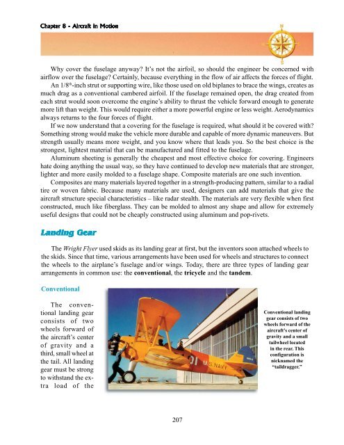
- Page 206 and 207: Chapter Chapter 8 8 - - Air Aircraf
- Page 208 and 209: Chapter Chapter 8 8 - - - Air Aircr
- Page 210 and 211: Chapter Chapter 8 8 - - Air Aircraf
- Page 214 and 215: Chapter Chapter 8 8 - - - Air Aircr
- Page 216 and 217: Chapter Chapter 8 8 - - Air Aircraf
- Page 218 and 219: Chapter Chapter 8 8 - - - Air Aircr
- Page 220 and 221: Chapter Chapter 8 8 - - - Air Aircr
- Page 222 and 223: Chapter Chapter 8 8 - - Air Aircraf
- Page 224 and 225: Chapter Chapter 8 8 - - Air Aircraf
- Page 226 and 227: Chapter Chapter 8 8 - - - Air Aircr
- Page 228 and 229: Chapter Chapter 8 8 - - Air Aircraf
- Page 230 and 231: Chapter Chapter 8 8 - - Air Aircraf
- Page 232 and 233: Chapter Chapter 8 8 - - Air Aircraf
- Page 234 and 235: Chapter Chapter Chapter Chapter Cha
- Page 236 and 237: Chapter Chapter 9 9 - - - Flight Fl
- Page 238 and 239: Chapter Chapter 9 9 - - - Flight Fl
- Page 240 and 241: Chapter Chapter 9 9 - - Flight Flig
- Page 242 and 243: Chapter Chapter 9 9 - - Flight Flig
- Page 244 and 245: Chapter Chapter 9 9 - - Flight Flig
- Page 246 and 247: Chapter Chapter 9 9 - - - Flight Fl
- Page 248 and 249: Chapter Chapter 9 9 - - Flight Flig
- Page 250 and 251: Chapter Chapter 9 9 - - Flight Flig
- Page 252 and 253: Chapter Chapter 9 9 - - - Flight Fl
- Page 254 and 255: Chapter Chapter Chapter 9 9 - - Fli
- Page 256 and 257: Chapter Chapter 9 9 - - Flight Flig
- Page 258 and 259: Chapter Chapter 9 9 - - - Flight Fl
- Page 260 and 261: Chapter Chapter 9 9 - - - Flight Fl
- Page 262 and 263:
Chapter Chapter 9 9 - - Flight Flig
- Page 264 and 265:
Chapter Chapter 9 9 - - - Flight Fl
- Page 266:
Chapter Chapter 9 9 - - - Flight Fl
- Page 269 and 270:
The The Airport Airport Airports co
- Page 271 and 272:
Control Control Control Control Con
- Page 273 and 274:
quick white flashes. This differenc
- Page 275 and 276:
MATCHING 1.Match the terms: a. runw
- Page 277 and 278:
airlines began flying more profitab
- Page 279 and 280:
produced in the greatest numbers. B
- Page 281 and 282:
Boeing Boeing Boeing Boeing Boeing
- Page 283 and 284:
percent more flights per day. Compa
- Page 285 and 286:
Swearingen Swearingen Swearingen Sw
- Page 287 and 288:
SELECT THE CORRECT ANSWER 1. The (7
- Page 289 and 290:
Chapter Chapter Chapter Chapter Cha
- Page 291 and 292:
Since World War II, a number of tra
- Page 293 and 294:
etractable) landing gear. The Skyha
- Page 295 and 296:
290
- Page 297 and 298:
A hot air balloon takes off from th
- Page 299 and 300:
Racing Racing Racing Racing Racing
- Page 301 and 302:
SELECT THE CORRECT ANSWER 1. (Ultra
- Page 303 and 304:
Chapter Chapter Chapter Chapter Cha
- Page 305 and 306:
In figuring the fuel efficiency of
- Page 307 and 308:
All of these aircraft carry a pilot
- Page 309 and 310:
However, remember during that hour
- Page 311 and 312:
The Canadair Challenger began as a
- Page 313 and 314:
commercial pilot certificate and an
- Page 315 and 316:
specially trained pilot then uses h
- Page 317 and 318:
5. Fill in the blanks with nontrans
- Page 319 and 320:
usually is able to carry either nuc
- Page 321 and 322:
aircraft. Weight is important becau
- Page 323 and 324:
capabilities. About the size of an
- Page 325 and 326:
Noncombatant Noncombatant Aircraf A
- Page 327 and 328:
OV-10A Bronco. This aircraft was sp
- Page 329 and 330:
MILITARY AIRCRAFT LETTER AND NUMBER
- Page 331 and 332:
C-17. The C-17 Globemaster III is t
- Page 333 and 334:
� combat aircraft � noncombat a
- Page 335 and 336:
15. To make up for the disadvantage
- Page 337 and 338:
Bell AH-1 HueyCobra. The AH-1 was d
- Page 339 and 340:
Sikorsky HH-3. Twin 1,500-horsepowe
- Page 341 and 342:
Companies supplying offshore oil pl
- Page 343 and 344:
Higher rotation speed and higher fo
- Page 345 and 346:
In war, there will always be situat
- Page 347 and 348:
Two methods are available for using
- Page 349 and 350:
In the 1980s, new technology, which
- Page 351 and 352:
7. Which of the following is not a
- Page 353 and 354:
maintenance of the airway system ov
- Page 355 and 356:
(transfer it) to another air traffi
- Page 357 and 358:
Center. The CAI operates the progra
- Page 359 and 360:
encouraging learning through its ma
- Page 361 and 362:
CAP Emergency Services 356 which we
- Page 363 and 364:
one of the largest airshows in the
- Page 365 and 366:
SELECT THE CORRECT ANSWER 1. The (F
- Page 367 and 368:
Chapter Chapter Chapter Chapter Cha
- Page 369 and 370:
APTITUDES AND AEROSPACE CAREERS Apt
- Page 371 and 372:
amount of exposure to these basic s
- Page 373 and 374:
Freshman and Sophomore Years: Engli
- Page 375 and 376:
Sophomore Year: Meteorology Science
- Page 377 and 378:
Scholarships are available to quali
- Page 379 and 380:
1. Be at least 17-years-old and not
- Page 381 and 382:
� aptitude � curricula � comm
- Page 383:
18. The _________ _________ _______
- Page 386 and 387:
Chapter Chapter 18 18 18 - - - The
- Page 388 and 389:
Chapter Chapter 18 18 - - The The A
- Page 390 and 391:
Chapter Chapter 18 18 - - The The A
- Page 392 and 393:
Chapter Chapter 18 18 - - The The A
- Page 394 and 395:
Chapter Chapter 18 18 18 - - The Th
- Page 396 and 397:
Chapter Chapter 18 18 - - The The A
- Page 398 and 399:
Chapter Chapter 18 18 - - The The A
- Page 400 and 401:
Chapter Chapter 18 18 18 - - - The
- Page 402 and 403:
Chapter Chapter 18 18 - - The The A
- Page 404 and 405:
Chapter Chapter 18 18 - - The The A
- Page 406 and 407:
Chapter Chapter 18 18 - - The The A
- Page 408 and 409:
Chapter Chapter 18 18 - - The The A
- Page 410 and 411:
Chapter Chapter 19- 19- W WWeather
- Page 412 and 413:
Chapter Chapter Chapter 19- 19- W W
- Page 414 and 415:
Chapter Chapter 19- 19- W WWeather
- Page 416 and 417:
Chapter Chapter 19- 19- W WWeather
- Page 418 and 419:
Chapter Chapter 19- 19- W WWeather
- Page 420 and 421:
Chapter Chapter 19- 19- W WWeather
- Page 422 and 423:
Chapter Chapter 19- 19- W WWeather
- Page 424 and 425:
Chapter Chapter 19- 19- W WWeather
- Page 426 and 427:
Chapter Chapter 19- 19- W WWeather
- Page 428 and 429:
Chapter Chapter Chapter Chapter Cha
- Page 430 and 431:
Chapter Chapter Chapter 20 20 - - A
- Page 432 and 433:
Chapter Chapter 20 20 - - A AAviati
- Page 434 and 435:
Chapter Chapter Chapter 20 20 - - A
- Page 436 and 437:
Chapter Chapter Chapter 20 20 - - A
- Page 438 and 439:
Chapter Chapter 20 20 - - A AAviati
- Page 440 and 441:
Chapter Chapter 20 20 - - A AAviati
- Page 442 and 443:
Chapter Chapter Chapter 20 20 - - A
- Page 444 and 445:
Chapter Chapter Chapter 20 20 - - A
- Page 446 and 447:
Chapter Chapter Chapter 20 20 - - A
- Page 449 and 450:
There is an explanation for everyth
- Page 451 and 452:
Even with improvements over the sti
- Page 453 and 454:
ecause of the centrifugal force cre
- Page 455 and 456:
A Demonstration of Newton’s Third
- Page 457 and 458:
module payload. Of course, the ulti
- Page 459 and 460:
Solid Fuel Propulsion System hot, e
- Page 461 and 462:
Let’s suppose we do not want to b
- Page 463 and 464:
MATCHING 7. Match the scientist wit
- Page 465 and 466:
With a few exceptions, propulsion s
- Page 467 and 468:
The chemical reaction of hydrogen a
- Page 469 and 470:
tube was known and employed in warf
- Page 471 and 472:
is used to start the ignition proce
- Page 473 and 474:
paint certain surfaces of the prope
- Page 475 and 476:
the precombustion chamber is ignite
- Page 477 and 478:
atomized and sufficiently diffused
- Page 479 and 480:
FILL IN THE BLANKS 7. Rust and corr
- Page 481 and 482:
In this chapter, we will look at wh
- Page 483 and 484:
and inversely proportional to the s
- Page 485 and 486:
inclination constant, precesses slo
- Page 487 and 488:
Suppose the mission of a payload re
- Page 489 and 490:
Burnout of the propellant system wi
- Page 491 and 492:
Earth, always maintaining the same
- Page 493 and 494:
Other Other Other Other Other Copla
- Page 495 and 496:
same as the Earth’s period of rot
- Page 497 and 498:
The launch vehicles used by the mil
- Page 499 and 500:
� orbits � trajectories � ine
- Page 502 and 503:
Space. The Final Frontier. These ar
- Page 504 and 505:
Chapter Chapter 24 24 - - Space Spa
- Page 506 and 507:
Chapter Chapter 24 24 - - - Space S
- Page 508 and 509:
Chapter Chapter 24 24 - - - Space S
- Page 510 and 511:
Chapter Chapter 24 24 - - - Space S
- Page 512 and 513:
Chapter Chapter Chapter 24 24 - - S
- Page 514 and 515:
Chapter Chapter 24 24 - - - Space S
- Page 516 and 517:
Chapter Chapter Chapter 24 24 - - S
- Page 518 and 519:
Chapter Chapter 24 24 - - Space Spa
- Page 520 and 521:
Chapter Chapter 24 24 - - - Space S
- Page 522 and 523:
Chapter Chapter 24 24 - - - Space S
- Page 524 and 525:
Chapter Chapter Chapter 24 24 - - -
- Page 526 and 527:
Chapter Chapter 24 24 - - Space Spa
- Page 528 and 529:
Chapter Chapter 25 25 - - Our Our S
- Page 530 and 531:
Chapter Chapter 25 25 - - Our Our S
- Page 532 and 533:
Chapter Chapter 25 25 - - Our Our S
- Page 534 and 535:
Chapter Chapter 25 25 - - Our Our S
- Page 536 and 537:
Chapter Chapter 25 25 - - Our Our S
- Page 538 and 539:
Chapter Chapter 25 25 - - Our Our S
- Page 540 and 541:
Chapter Chapter 25 25 - - Our Our S
- Page 542 and 543:
Chapter Chapter 25 25 - - Our Our S
- Page 544 and 545:
Chapter Chapter 25 25 - - Our Our S
- Page 546 and 547:
Chapter Chapter 25 25 - - Our Our S
- Page 548 and 549:
Chapter Chapter 25 25 - - Our Our S
- Page 550 and 551:
Chapter Chapter 25 25 - - Our Our S
- Page 552 and 553:
Chapter Chapter 25 25 - - Our Our S
- Page 554 and 555:
Chapter Chapter 25 25 - - Our Our S
- Page 556 and 557:
At the end of World War II, the tea
- Page 558 and 559:
Chapter Chapter 26 26 - - Unmanned
- Page 560 and 561:
Chapter Chapter Chapter 26 26 - - U
- Page 562 and 563:
Chapter Chapter 26 26 - - Unmanned
- Page 564 and 565:
Chapter Chapter 26 26 - - Unmanned
- Page 566 and 567:
Chapter Chapter 26 26 - - Unmanned
- Page 568 and 569:
Chapter Chapter 26 26 - - Unmanned
- Page 570 and 571:
Chapter Chapter Chapter 26 26 26 -
- Page 572 and 573:
Chapter Chapter 26 26 - - Unmanned
- Page 574 and 575:
Chapter Chapter 26 26 - - Unmanned
- Page 576 and 577:
Chapter Chapter 26 26 26 - - Unmann
- Page 578 and 579:
Chapter Chapter 26 26 26 - - Unmann
- Page 580 and 581:
Chapter Chapter 26 26 26 - - Unmann
- Page 582 and 583:
Chapter Chapter 26 26 26 - - Unmann
- Page 584 and 585:
Chapter Chapter 26 26 26 - - Unmann
- Page 586 and 587:
Chapter Chapter 26 26 26 - - Unmann
- Page 588 and 589:
The space race between the United S
- Page 590 and 591:
Chapter Chapter 27 27 - - Manned Ma
- Page 592 and 593:
Chapter Chapter 27 27 - - Manned Ma
- Page 594 and 595:
Chapter Chapter 27 27 - - Manned Ma
- Page 596 and 597:
Chapter Chapter 27 27 - - Manned Ma
- Page 598 and 599:
Chapter Chapter 27 27 - - Manned Ma
- Page 600 and 601:
Chapter Chapter 27 27 - - Manned Ma
- Page 602 and 603:
Chapter Chapter Chapter 27 27 - - M
- Page 604 and 605:
Chapter Chapter Chapter 27 27 - - M
- Page 606 and 607:
Chapter Chapter 27 27 - - Manned Ma
- Page 608 and 609:
Chapter Chapter 27 27 - - Manned Ma
- Page 610 and 611:
Chapter Chapter 27 27 - - Manned Ma
- Page 612 and 613:
27. Tonkin Gulf Resolution, Johnson
- Page 614 and 615:
13. training routes 14. true course
- Page 616 and 617:
CHAPTER 16 1. CAB 2. FSS 3. NAFEC 4
- Page 618 and 619:
CHAPTER 21 1. Gravity 2. Galileo 3.
- Page 620 and 621:
9. Weather—A, C, E, G; Multi-Spec
- Page 622 and 623:
Aurora australis - colored lights,
- Page 624 and 625:
D Dead reckoning - involves the sys
- Page 626 and 627:
Haze - a concentration of water vap
- Page 628 and 629:
Magnetic course - the course accord
- Page 630 and 631:
Prime meridian - the great circle l
- Page 632 and 633:
Strategic airlift - transportation
- Page 634 and 635:
Weather - the day-to-day changes in
- Page 636 and 637:
C-54, 118, 124 C-69, 124 C-130 Herc
- Page 638 and 639:
VS 300, 63 X-1, 129,176 X-15, 159-1
- Page 640 and 641:
Eichstadt, Konrad 445 Eighth Air Fo
- Page 642 and 643:
Manning, Captain Harry, 9 Mannock,
- Page 644 and 645:
soaring, 292-293 solar radiation 39
- Page 646:
This textbook was jointly produced