Underwater Robots - Gianluca Antonelli.pdf
Underwater Robots - Gianluca Antonelli.pdf
Underwater Robots - Gianluca Antonelli.pdf

Create successful ePaper yourself
Turn your PDF publications into a flip-book with our unique Google optimized e-Paper software.
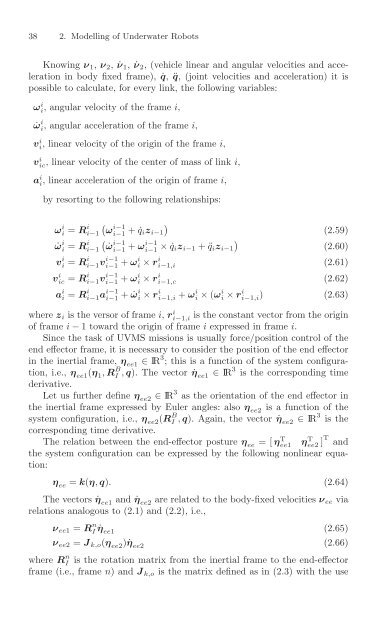
38 2. Modelling of <strong>Underwater</strong> <strong>Robots</strong><br />
Knowing ν 1 , ν 2 , ˙ν 1 , ˙ν 2 ,(vehicle linear and angular velocities and acceleration<br />
in body fixed frame), ˙q , ¨q ,(joint velocities and acceleration) it is<br />
possible to calculate, for every link, the following variables:<br />
ω i i ,angular velocity ofthe frame i ,<br />
˙ω i i ,angular acceleration ofthe frame i ,<br />
v i i ,linear velocity ofthe origin ofthe frame i ,<br />
v i ic ,linear velocity ofthe center of mass of link i ,<br />
a i i ,linear acceleration ofthe origin offrame i ,<br />
by resorting to the following relationships:<br />
ω i i = R i � i − 1<br />
i − 1 ω i − 1 +˙q �<br />
i z i − 1<br />
˙ω<br />
(2.59)<br />
i i = R i � i − 1 i − 1<br />
i − 1 ˙ω i − 1 + ω i − 1 × ˙q �<br />
i z i − 1 +¨q i z i − 1<br />
(2.60)<br />
v i i = R i i − 1<br />
i − 1 v i − 1 + ω i i × r i i − 1 ,i<br />
(2.61)<br />
v i ic = R i i − 1<br />
i − 1 v i − 1 + ω i i × r i i − 1 ,c<br />
(2.62)<br />
a i i = R i i − 1<br />
i − 1 a i − 1 + ˙ω i i × r i i − 1 ,i + ω i i × ( ω i i × r i i − 1 ,i) (2.63)<br />
where z i is the versor offrame i , r i i − 1 ,i<br />
of frame i − 1toward the origin offrame i expressed in frame i .<br />
Since the task of UVMS missions is usually force/position control of the<br />
end effector frame, it is necessary to consider the position of the end effector<br />
in the inertial frame, η ee1 ∈ IR 3 ;this is afunction ofthe system configuration,<br />
i.e., η ee1 ( η 1 , R B I , q ). The vector ˙η ee1 ∈ IR 3 is the corresponding time<br />
derivative.<br />
Let us further define η ee2 ∈ IR 3 as the orientation of the end effector in<br />
the inertial frame expressed by Euler angles: also η ee2 is afunction ofthe<br />
system configuration, i.e., η ee2 ( R B I , q ). Again, the vector ˙η ee2 ∈ IR 3 is the<br />
is the constant vector from the origin<br />
corresponding time derivative.<br />
The relation between the end-effector posture η ee =[η T ee1 η T ee2 ] T and<br />
the system configuration can be expressed by the following nonlinear equation:<br />
η ee = k ( η , q ) . (2.64)<br />
The vectors ˙η ee1 and ˙η ee2 are related to the body-fixed velocities ν ee via<br />
relations analogous to(2.1) and (2.2), i.e.,<br />
ν ee1 = R n I ˙η ee1<br />
ν ee2 = J k,o ( η ee2 ) ˙η ee2<br />
(2.65)<br />
(2.66)<br />
where R n I is the rotation matrix from the inertial frame to the end-effector<br />
frame (i.e., frame n )and J k,o is the matrix defined as in (2.3) with the use