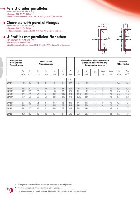
Fers U à ailes parallèlesDimensions: NF A 45-255 (1983)Tolérances: EN 10279: 2000Etat de surface conforme à EN 10163-3: 1991, classe C, sous-classe 1Channels with parallel flangesDimensions: NF A 45-255 (1983)Tolerances: EN 10279: 2000Surface condition according to EN 10163-3: 1991, class C, subclass 1s sbrey s45 o d h iU-Profiles mit parallelen FlanschenAbmessungen: NF A 45-255 (1983)Toleranzen: EN 10279: 2000Oberflächenbeschaffenheit gemäß EN 10163-3: 1991, Klasse C, Untergruppe 1yhyy mt wt fzzDésignationDesignationBezeichnungDimensionsAbmessungenDimensions de constructionDimensions for detailingKonstruktionsmaßeSurfaceOberflächeGkg/mhmmbmmt wmmt fmmrmmAmm 2h immdmmØe minmme maxmmA Lm 2 /mA Gm 2 /tx10 2UAP 80* 8,38 80 45 5 8 8 10,7 64 48 - - - 0,32 38,56UAP 100* 10,5 100 50 5,5 8,5 8,5 13,4 83 66 M 10 25 30 0,38 36,35UAP 130* 13,7 130 55 6 9,5 9,5 17,5 111 92 M 10 27 35 0,46 33,48UAP 150* 17,9 150 65 7 10,25 10,25 22,9 129,5 109 M 16 33 36 0,54 29,96UAP 175* 21,2 175 70 7,5 10,75 10,75 27,0 153,5 132 M 16 34 41 0,61 28,52UAP 200* 25,1 200 75 8 11,5 11,5 32,0 177 154 M 16 35 46 0,67 26,86UAP 220* 28,5 220 80 8 12,5 12,5 36,3 195 170 M 16 36 51 0,73 25,75UAP 250 34,4 250 85 9 13,5 13,5 43,8 223 196 M 22 43 47 0,81 23,57UAP 300 46,0 300 100 9,5 16 16 58,6 268 236 M 27 51 53 0,97 21,04* Tonnage minimum et conditions de livraison nécessitent un accord préalable.78* Minimum tonnage and delivery conditions upon agreement.* Die Mindestmengen pro Bestellung sowie die Lieferbedingungen sind im Voraus zu vereinbaren.
Notations pages 211-215 / Bezeichnungen Seiten 211-215DésignationDesignationBezeichnungGkg/mI ymm 4Valeurs statiques / Section properties / Statische Kennwerteaxe fort y-ystrong axis y-ystarke Achse y-yW el.y W■pl.y i ymm 3 mm 3 mmA vzmm 2axe faible z-zweak axis z-zschwache Achse z-zI zmm 4W el.zmm 3W pl.z’mm 3i zmms smmI tmm 4I wmm 6y smmUAPy mmmClassificationENV 1993-1-1pure purebending y-y compressionS 235S 355S 235S 355EN 10025:1993EN 10113-3:1993EN 10225:2001x10 4 x10 3 x10 3 x10 x10 2 x10 4 x10 3 x10 3 x10 x10 4 x10 9 x10 x10UAP 80 8,38 107,1 26,78 31,87 3,17 4,51 21,33 7,38 13,64 1,41 17,7 1,90 0,18 1,61 3,17 1 1 1 1 ✔UAP 100 10,5 209,5 41,90 49,59 3,96 6,07 32,83 9,95 18,47 1,57 19,0 2,65 0,45 1,70 3,38 1 1 1 1 ✔UAP 130 13,7 459,6 70,70 83,51 5,12 8,52 51,34 13,78 25,55 1,71 21,1 4,15 1,22 1,77 3,56 1 1 1 1 ✔UAP 150 17,9 796,1 106,1 125,3 5,90 11,28 93,25 20,97 38,78 2,02 23,3 6,51 2,99 2,05 4,15 1 1 1 1 ✔UAP 175 21,2 1270 145,1 171,5 6,85 13,97 126,4 25,92 47,47 2,16 24,5 8,43 5,62 2,12 4,32 1 1 1 1 ✔UAP 200 25,1 1946 194,6 230,1 7,80 16,97 169,7 32,13 58,29 2,30 26,2 11,24 9,98 2,22 4,53 1 1 1 1 ✔UAP 220 28,5 2710 246,4 289,9 8,64 18,83 222,3 39,68 72,56 2,48 27,8 14,40 15,82 2,40 4,94 1 1 1 1 ✔UAP 250 34,4 4136 330,9 391,8 9,72 23,89 295,4 48,87 87,65 2,60 30,4 20,38 27,43 2,45 5,04 1 1 1 1 ✔UAP 300 46,0 8170 544,7 639,3 11,81 30,64 562,1 79,88 145,8 3,10 34,9 36,30 75,04 2,96 6,17 1 1 1 1 ✔■■■W pl.y est calculé selon l’hypothèse d’un diagramme de contraintes bi-rectangulaire et n’est applicable que si deux ou plusieurs fers U sont associés de façonà constituer une section doublement symétrique pour laquelle un moment de flexion agissant dans le plan du centre de gravité n’engendre pas de torsion.W pl.y is determined assuming a bi-rectangular stress block distribution. Thus, the given value applies only if two or more channels are combined in sucha way to form a doubly symmetric cross-section so that the bending moment acting in the plane of the centre of gravity will not lead to torsion.Für die Berechnung von W pl.y wurde eine doppelrechteckige Spannungsverteilung angenommen. Der angegebene Wert ist daher nur anwendbar,wenn zwei oder mehr U-Profile so miteinander kombiniert sind, dass sie einen doppelsymmetrischen Querschnitt bilden, womit ein Biegemoment, das inder Schwerpunktebene angreift, keine Torsion hervorruft.79