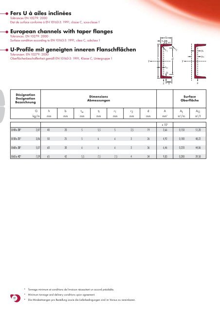
Fers U à ailes inclinéesTolérances EN 10279: 2000Etat de surface conforme à EN 10163-3: 1991, classe C, sous-classe 1European channels with taper flangesTolerances: EN 10279: 2000Surface condition according to EN 10163-3: 1991, class C, subclass 1s sb45 o dU-Profile mit geneigten inneren FlanschflächenToleranzen: EN 10279: 2000Oberflächenbeschaffenheit gemäß EN 10163-3: 1991, Klasse C, Untergruppe 1yhr 1r 2yy sy mt wt fz zuDésignationDesignationBezeichnungDimensionsAbmessungenSurfaceOberflächeGhbt wt fr 1r 2dAA LA Gkg/mmmmmmmmmmmmmmmmm 2m 2 /mm 2 /tU 40 x 20* 2,87 40 20 5 5,5 5 2,5 19 3,66 0,150 51,20x10 2U 50 x 25* 3,86 50 25 5 6 6 3 26 4,92 0,180 48,22U 60 x 30* 5,07 60 30 6 6 6 3 36 6,46 0,220 44,06U 65 x 42* 7,09 65 42 5,5 7,5 7,5 4 34 9,03 0,280 39,58* Tonnage minimum et conditions de livraison nécessitent un accord préalable.82* Minimum tonnage and delivery conditions upon agreement.* Die Mindestmengen pro Bestellung sowie die Lieferbedingungen sind im Voraus zu vereinbaren.
UNotations pages 211-215 / Bezeichnungen Seiten 211-215DésignationDesignationBezeichnungGkg/mI ymm 4Valeurs statiques / Section properties / Statische Kennwerteaxe fort y-ystrong axis y-ystarke Achse y-yW el.y W■pl.y i ymm 3 mm 3 mmA vzmm 2axe faible z-zweak axis z-zschwache Achse z-zI zmm 4W el.zmm 3W pl.z’mm 3i zmms smmI tmm 4I wmm 6y smmy mmmClassificationENV 1993-1-1pure purebending y-y compressionS 235S 355S 235S 355EN 10025:1993EN 10113-3:1993EN 10225:2001x10 4 x10 3 x10 3 x10 x10 2 x10 4 x10 3 x10 3 x10 x10 4 x10 9 x10 x10U 40 x 20 2,87 7,62 3,81 4,91 1,44 1,96 1,15 0,86 1,65 0,56 13,4 0,39 0,003 0,67 1,03 1 1 1 1 ✔U 50 x 25 3,86 16,9 6,76 8,52 1,85 2,52 2,50 1,48 2,84 0,71 14,6 0,59 0,009 0,81 1,36 1 1 1 1 ✔U 60 x 30 5,07 31,7 10,56 13,3 2,21 3,54 4,53 2,16 4,19 0,84 15,8 0,89 0,024 0,90 1,52 1 1 1 1 ✔U 65 x 42 7,09 57,7 17,77 21,7 2,53 3,68 14,1 5,06 9,38 1,25 18,0 1,61 0,082 1,39 2,58 1 1 1 1 ✔■■■W pl.y est calculé selon l’hypothèse d’un diagramme de contraintes bi-rectangulaire et n’est applicable que si deux ou plusieurs fers U sont associés de façonà constituer une section doublement symétrique pour laquelle un moment de flexion agissant dans le plan du centre de gravité n’engendre pas de torsion.W pl.y is determined assuming a bi-rectangular stress block distribution. Thus, the given value applies only if two or more channels are combined in sucha way to form a doubly symmetric cross-section so that the bending moment acting in the plane of the centre of gravity will not lead to torsion.Für die Berechnung von W pl.y wurde eine doppelrechteckige Spannungsverteilung angenommen. Der angegebene Wert ist daher nur anwendbar,wenn zwei oder mehr U-Profile so miteinander kombiniert sind, dass sie einen doppelsymmetrischen Querschnitt bilden, womit ein Biegemoment, das inder Schwerpunktebene angreift, keine Torsion hervorruft.83