SERVICEHANDBUCH - Knott Brake Company
SERVICEHANDBUCH - Knott Brake Company
SERVICEHANDBUCH - Knott Brake Company

Erfolgreiche ePaper selbst erstellen
Machen Sie aus Ihren PDF Publikationen ein blätterbares Flipbook mit unserer einzigartigen Google optimierten e-Paper Software.
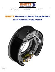
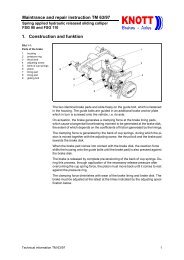
1. INTRODUCTION<br />
The instructions for use and maintenance given below,<br />
with operating regulations, relate to KNOTT chassis<br />
components. They form a part of our warranty conditions.<br />
In addition, the relevant operating regulations of<br />
the vehicle manufacturer must be complied with.<br />
To ensure continuing reliability and road safety in traffic,<br />
the maintenance tasks have to be performed at the<br />
prescribed intervals.<br />
Maintenance, repairs and replacement of wearing parts<br />
for the chassis and the braking system may only be<br />
performed by a qualified garage.<br />
Only original KNOTT spares may be used in order to<br />
a) ensure proper functioning and safety,<br />
b) preserve all rights under the guarantee and warranty,<br />
c) prevent the operating licence from becoming invalid<br />
under national and international<br />
regulations.<br />
The braking system, particularly the over-run hitch<br />
and the wheel brakes, plus the draw poles, have been<br />
tested according to the relevant EC guidelines and may<br />
only be used in the licensed combination.<br />
KNOTT chassis consist of the ball coupler, the over-run<br />
hitch, the transmission system, the wheel brakes in<br />
conjunction with KNOTT rubber, torsion thrust spring<br />
and torsion spring axles, plus the drawgear, the draw<br />
poles and/or the side bars as the case may be.<br />
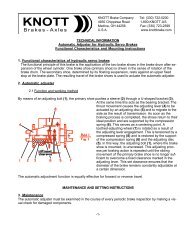
2. BALL COUPLERS<br />
All KNOTT ball couplers are equipped with a safety<br />
check indicator. This consists of clearly embossed<br />
symbols to which a red-green-red label with the same<br />
symbols has been glued, and an indicator button. If the<br />
label is damaged, it can be removed and the embossed<br />
symbols used, or the label can be replaced, in which<br />
case the lines dividing the zones on the label and the<br />
embossing must be aligned.<br />
2.1 Uncoupling<br />
To open, pull the coupling handle upwards and then<br />
turn it forwards.<br />
56<br />
� INSTRUCTIONS FOR USE AND MAINTENANCE<br />
1<br />
ZZZZ iiii eeee hhhh ennnn<br />
DDDD rehen<br />
- + X<br />
2<br />
The coupling automatically remains in "open” position,<br />
in which the indicator button points to the red field with<br />
the large "X”.<br />
�<br />
�<br />
The trailer must never be driven in this<br />
position!<br />
!Caution:<br />
Never insert your fingers in the open ball<br />
coupler. Even slight pressure on the<br />
sphere can trigger the spring-load closing<br />
mechanism and result in injury to the fingers.<br />
2.2 Coupling<br />
To couple the trailer, place the open ball coupler (X position)<br />
on the ball of the towing vehicle so that it clicks<br />
into place audibly.<br />
When the ball coupler has clicked properly into place,<br />
the indicator jumps to the green zone marked "+”.<br />
Z iehen<br />
D rehen<br />
- + X<br />
3<br />
After coupling, it is essential to use the indicator check<br />
that the ball coupler has clicked into place on the ball<br />
correctly.<br />
If the indicator is in the green "+” zone, the ball coupler<br />
is correctly closed and locked, and the ball on the<br />
vehicle still has sufficient wearing reserves.<br />
� There is no safe connection between your<br />
towing vehicle and the trailer unless this