SERVICEHANDBUCH - Knott Brake Company
SERVICEHANDBUCH - Knott Brake Company
SERVICEHANDBUCH - Knott Brake Company

Erfolgreiche ePaper selbst erstellen
Machen Sie aus Ihren PDF Publikationen ein blätterbares Flipbook mit unserer einzigartigen Google optimierten e-Paper Software.
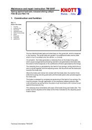
INSTRUCTIONS FOR USE AND MAINTENANCE<br />
In special axles with additional mounting points, these<br />
also have to be lubricated appropriately.<br />
6.7 Draw poles / side bars<br />
Damaged or deformed side bars, particularly the draw<br />
poles, must be replaced immediately. These components<br />
must never be adjusted for further use.<br />
With certain chassis types, the side bars and draw<br />
poles are connected with special screws.<br />
All screw joints must be checked at the regular maintenance<br />
intervals and if necessary tightened. Please<br />
note the permitted tightening torque.<br />
6.8 Height adjuster<br />
(height-adjustable drawgear only)<br />
The radial teething must be cleaned of frictional corrosion<br />
and other dirt at least once a year to preserve a<br />
good fit.<br />
The threaded bolts and articulated points must be<br />
lubricated once a year, or whenever they become stiff.<br />
The tightening torque of the nuts must be checked.<br />
7 STOPPING<br />
7.1.1 With over-run hitch with a "KH” or "GF” handbrake,<br />
it is sufficient to pull the handbrake lever through<br />
the dead point. The spring load will then ensure that the<br />
wheel brakes are held tightly enough.<br />
7.1.2 With over-run hitches with "HF” ratchet handbrake<br />
levers, it is essential to pull the lever right<br />
up to the last tooth. This is necessary in order<br />
� to have sufficient reserve movement to bridge<br />
the automatic reverse in the spring load.<br />
7.2 Place wedges under the trailer to hold it in place.<br />
60<br />
When stopping for prolonged periods, particularly<br />
in cold and wet weather, chock<br />
the trailer with standard car/trailer wheel<br />
chocks - without applying hand brake.<br />
8 COUPLING / UNCOUPLING<br />
8.1 Coupling<br />
8.1.1 Check that the ball coupler is open (see 2.1).<br />
8.1.2 Check that the coupling height of the trailer is<br />
approx. 5cm above that of the towing vehicle.<br />
If necessary you can adjust the height by<br />
means of the support wheel. � 8.1.3 Reverse the towing vehicle towards the<br />
parked and braked trailer until the ball coupler<br />
is almost exactly over the ball on the vehicle.<br />
For safety reasons, ensure that no one<br />
comes between the trailer and the towing<br />
vehicle.<br />
8.1.4 Remove the wedges from under the trailer.<br />
8.1.5 Release the trailer’s handbrake.<br />
8.1.5.1 With over-run hitches with "KH” or "GF” handbrake<br />
levers, the lever only needs to be pulled forwards<br />
into home position.<br />
No additional locks or buttons need releasing or pressing.<br />
With over-run hitches with a pull-out handbrake lever,<br />
the lever must first be pulled out to its maximum<br />
length. Then the safety brake can be released easily.<br />
Finally the handbrake lever must be pushed back into<br />
its shortest possible position.<br />
8.1.5.2 With over-run hitches with "HF” ratchet levers,<br />
the release button on the handbrake lever must be<br />
pressed before the lever can be put in release position.<br />
The amount of strength needed to press the button can<br />
be reduced by simultaneously pressing the handbrake<br />
lever slightly in the direction of tensioning.<br />
8.1.6 Pull the trailer with the ball coupler exactly over<br />
the ball.<br />
8.1.7 Slowly lower the drawgear until the ball coupler<br />
audibly clicks into place on the ball.<br />
Please check that the coupling is properly closed using<br />
the markings on the ball coupler (see 2.2).<br />
8.1.8 You can now turn the support wheel right up to<br />
the top position.<br />
8.1.9 Loop the safety cable once round the ball neck<br />
and clip the spring hook onto the cable.<br />
8.1.10 Plug the trailer’s light plug in the socket on<br />
the towing vehicle and check that the light system is<br />
working.<br />
8.2 To uncouple, please go through these steps in<br />
reverse order, also following the instructions on parking,<br />
no. 7.<br />
9 ADJUSTING COUPLING HEIGHT (HEIGHT-<br />
ADJUSTABLE DRAWGEAR ONLY)<br />
The angle between the drawgear and the transition<br />
piece can be adjusted from -10∞ to +49∞. The adjustable<br />
articulated connection between the drawgear<br />
and the transition piece, and between the over-run hitch<br />
and the transition piece, is by means of tooth tips or<br />
holding pieces with serrations or radial teeth.<br />
The radial teeth are joined by connecting screws. The<br />
nut must be tightened using the prescribed tightening<br />
torque to achieve a play-free join that transmits<br />
� torque. The tightening torque depends on the<br />
permitted total weight of the trailer and on the