Alesis Micron Owners Manual.pdf - Fdiskc
Alesis Micron Owners Manual.pdf - Fdiskc
Alesis Micron Owners Manual.pdf - Fdiskc
Create successful ePaper yourself
Turn your PDF publications into a flip-book with our unique Google optimized e-Paper software.
70<br />
6 Programs<br />
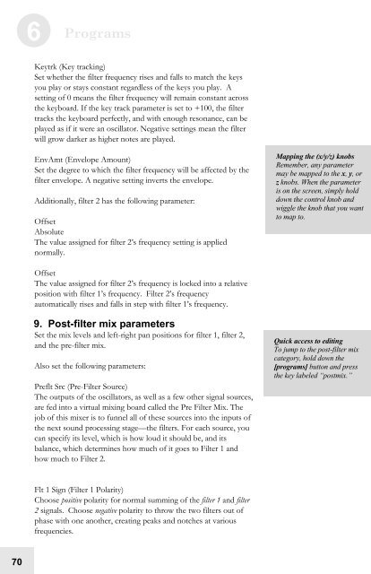
Keytrk (Key tracking)<br />
Set whether the filter frequency rises and falls to match the keys<br />
you play or stays constant regardless of the keys you play. A<br />
setting of 0 means the filter frequency will remain constant across<br />
the keyboard. If the key track parameter is set to +100, the filter<br />
tracks the keyboard perfectly, and with enough resonance, can be<br />
played as if it were an oscillator. Negative settings mean the filter<br />
will grow darker as higher notes are played.<br />
EnvAmt (Envelope Amount)<br />
Set the degree to which the filter frequency will be affected by the<br />
filter envelope. A negative setting inverts the envelope.<br />
Additionally, filter 2 has the following parameter:<br />
Offset<br />
Absolute<br />
The value assigned for filter 2’s frequency setting is applied<br />
normally.<br />
Offset<br />
The value assigned for filter 2’s frequency is locked into a relative<br />
position with filter 1’s frequency. Filter 2’s frequency<br />
automatically rises and falls in step with filter 1’s frequency.<br />
9. Post-filter mix parameters<br />
Set the mix levels and left-right pan positions for filter 1, filter 2,<br />
and the pre-filter mix.<br />
Also set the following parameters:<br />
Preflt Src (Pre-Filter Source)<br />
The outputs of the oscillators, as well as a few other signal sources,<br />
are fed into a virtual mixing board called the Pre Filter Mix. The<br />
job of this mixer is to funnel all of these sources into the inputs of<br />
the next sound processing stage—the filters. For each source, you<br />
can specify its level, which is how loud it should be, and its<br />
balance, which determines how much of it goes to Filter 1 and<br />
how much to Filter 2.<br />
Flt 1 Sign (Filter 1 Polarity)<br />
Choose positive polarity for normal summing of the filter 1 and filter<br />
2 signals. Choose negative polarity to throw the two filters out of<br />
phase with one another, creating peaks and notches at various<br />
frequencies.<br />
Mapping the (x/y/z) knobs<br />
Remember, any parameter<br />
may be mapped to the x, y, or<br />
z knobs. When the parameter<br />
is on the screen, simply hold<br />
down the control knob and<br />
wiggle the knob that you want<br />
to map to.<br />
Quick access to editing<br />
To jump to the post-filter mix<br />
category, hold down the<br />
[programs] button and press<br />
the key labeled “postmix.”


