Axial innen engl - TLT Turbo GmbH
Axial innen engl - TLT Turbo GmbH
Axial innen engl - TLT Turbo GmbH

Create successful ePaper yourself
Turn your PDF publications into a flip-book with our unique Google optimized e-Paper software.
Am Weinberg 68 · D-36251 Bad Hersfeld/Germany<br />
Phone: +49.6621.950-0 · Fax: +49.6621.950-100<br />
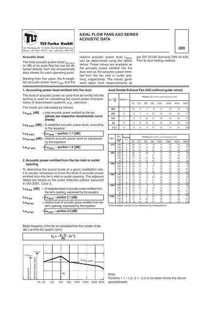
Acoustic level<br />
The total acoustic power level LW.Vent. (in dB) of an axial-flow fan can be obtained<br />
directly from the characteristic<br />
data sheets for each operating point.<br />
Starting from this value, the A-weighted<br />
acoustic power level LWA and the<br />
1. Acousting power level emitted into the duct<br />
The level of acoustic power an axial-flow fan emits into the<br />
ducting is used for calculating the sound power characteristics<br />
of downstream systems, e.g., silencers.<br />
The levels are calculated as follows:<br />
Lwvent. [dB] = total acoustic power emitted by the fan,<br />
(please see respective characteristic curve<br />
sheets)<br />
LwA vent. [dB] = A-weighted acoustic power level, according<br />
to the equation<br />
Lw A vent.<br />
= Lw vent. – portion 1.1 [dB]<br />
Lw rel vent. [dB]= relative acoustic power level as expressed<br />
by the equation<br />
Lw rel vent.<br />
= Lw vent. – portion 1.2 [dB]<br />
2. Acoustic power emitted from the fan inlet or outlet<br />
opening<br />
To determine the sound levels at a given installation site,<br />
it is usually necessary to know the level of acoustic power<br />
emitted from the fan’s inlet or outlet opening. The adjacent<br />
tables are based on the outlet reflection pattern assumed<br />
in VDI 2081, Case 2.<br />
LwA op. [dB] = A-weighted level of acoustic power emitted from<br />
the fan’s opening, expressed by the equation<br />
Lw A op.<br />
Lw rel op.<br />
Lw rel op.<br />
Lwvent. LwAvent. Amount A<br />
Amount-linear level<br />
= Lw vent. – portion 2.1 [dB]<br />
= relative level of acoustic power emitted from the<br />
fan’s opening, expressed by the equation<br />
= Lw vent. – portion 2.2 [dB]<br />
Blade frequency of the fan ist calculated from the number of blades<br />
z and the fan speed n [rpm].<br />
fD = –––––– [s-1 z · n<br />
]<br />
60<br />
fD<br />
Hz<br />
63 125 250 500 1000 2000 4000 8000<br />
AXIAL FLOW FANS AXO SERIES<br />
ACOUSTIC DATA<br />
relative acoustic power level L Wrel.<br />
can be determined using the tables<br />
below. These values are available as<br />
the acoustic power emitted into the<br />
duct and as the acoustic power emitted<br />
from the fan inlet or outlet opening,<br />
respectively. The values given<br />
were taken from measurements as<br />
Lw rel.vent.<br />
z · n<br />
fD = ––––<br />
60<br />
500<br />
250<br />
125<br />
63<br />
31,5<br />
Portion 1.1<br />
4<br />
6<br />
7<br />
8<br />
8<br />
020<br />
per EN 25136 (formerly DIN 45 635,<br />
Part 9) duct testing method.<br />
<strong>Axial</strong> Smoke Exhaust Fan AXO (without guide vanes)<br />
Size*<br />
315<br />
400<br />
500<br />
630<br />
800<br />
1000<br />
fD =<br />
z · n<br />
60<br />
500<br />
250<br />
125<br />
500<br />
250<br />
125<br />
63<br />
500<br />
250<br />
125<br />
63<br />
500<br />
250<br />
125<br />
63<br />
500<br />
250<br />
125<br />
63<br />
250<br />
125<br />
63<br />
Portion<br />
2.1<br />
4<br />
6<br />
8<br />
4<br />
6<br />
7<br />
8<br />
4<br />
6<br />
7<br />
8<br />
4<br />
6<br />
7<br />
8<br />
4<br />
6<br />
7<br />
8<br />
6<br />
7<br />
8<br />
Portion 1.2 at mid-octave frequency [Hz]<br />
63 125 250 500 1000 2000 4000 8000<br />
12 9 7 5 11 12 14 15<br />
9 7 4 10 12 13 15 17<br />
6 4 10 11 13 14 16 21<br />
2 8 10 11 13 15 19 24<br />
6 8 9 11 13 17 21 26<br />
Portion 2.2 at mid-octave frequency [Hz]<br />
63 125 250 500 1000 2000 4000 8000<br />
24 17 11 6 11 12 14 15<br />
21 15 8 12 12 13 15 17<br />
18 12 14 13 13 14 16 21<br />
22 16 10 5 11 12 14 15<br />
20 13 7 11 12 13 15 17<br />
17 10 13 12 13 14 16 21<br />
13 15 13 12 13 15 19 24<br />
21 14 9 5 11 12 14 15<br />
18 12 6 11 12 13 15 17<br />
15 9 11 11 13 14 16 21<br />
12 13 12 12 13 15 19 24<br />
20 13 8 5 11 12 14 15<br />
17 11 6 10 12 13 15 17<br />
14 8 11 11 13 14 16 21<br />
10 12 11 11 13 15 19 24<br />
18 12 8 5 11 12 14 15<br />
15 10 5 10 12 13 15 17<br />
12 7 10 11 13 14 16 21<br />
9 11 11 11 13 15 19 24<br />
14 9 5 10 12 13 15 17<br />
11 6 10 11 13 14 16 21<br />
8 10 10 11 13 15 19 24<br />
*Intermediate values to be obtained by interpolation.<br />
Note:<br />
Portions 1.1 / 1.2 / 2.1 / 2.2 to be taken frome the above<br />
spreadsheets.