Axial innen engl - TLT Turbo GmbH
Axial innen engl - TLT Turbo GmbH
Axial innen engl - TLT Turbo GmbH

Create successful ePaper yourself
Turn your PDF publications into a flip-book with our unique Google optimized e-Paper software.
Am Weinberg 68 · D-36251 Bad Hersfeld/Germany<br />
Phone: +49.6621.950-0 · Fax: +49.6621.950-100<br />
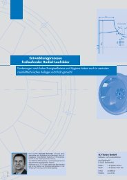
Drive motors<br />
<strong>Axial</strong>-flow fans of the AXO/AXN type<br />
are powered by surface-cooled motors<br />
according to IEC standards. Up<br />
to motor size 180, standard motors<br />
with type V1, B14 or B5 flanges are<br />
used, depending on the mounting position<br />
(AXO types are always supplied<br />
with B3 flanges). From motor size 200<br />
upwards, standard B3, V5 or V6 footmounted<br />
units are selected, again depending<br />
on the mounting position.<br />
These motors meet VDE 0530 specifications<br />
for electrical machinery, protection<br />
class IP 44, insulation class B,<br />
fitted with noise-tested antifriction<br />
bearings.<br />
Standard versions of these axial-flow<br />
fans are rated for a maximum operating<br />
temperature of 70°C since their<br />
impeller material is not resistant to<br />
higher thermal loads.<br />
Motor bearings require periodic regreasing.<br />
For guidance, the following<br />
lubrication intervals are given:<br />
Motor sizes 63 - 100<br />
n = 3000 rpm 5 000 operating hours<br />
n = 1500 rpm 10 000 operating hours<br />
n = 1000 rpm 20 000 operating hours<br />
n = 750 rpm 20 000 operating hours<br />
Motor sizes 112 - 160<br />
n = 3000 rpm 4 000 operating hours<br />
n = 1500 rpm 8 000 operating hours<br />
n = 1000 rpm 16 000 operating hours<br />
n = 750 rpm 16 000 operating hours<br />
Motor sizes 180 & 200<br />
n = 1500 rpm 5 000 operating hours<br />
n = 1000 rpm 7 000 operating hours<br />
n = 750 rpm 10 000 operating hours<br />
Motor sizes 225 - 280<br />
n = 1500 rpm 2 500 operating hours<br />
n = 1500 rpm 4 000 operating hours<br />
n = 750 rpm 6 000 operating hours<br />
AXIAL FLOW FANS<br />
ELECTRICAL NOTES<br />
GENERAL / MOTOR PROTECTION<br />
In any case, the motor manufacturer's<br />
detailed instructions must be observed<br />
(see motor nameplate). Motors<br />
up to size 200 in standard version<br />
have no relubrication device, on these<br />
motors bearing housings must be<br />
opened to apply new grease. Motors<br />
of size 225 and upwards have a relubricating<br />
device with grease valve.<br />
Single-speed motors can be run on<br />
230 V or 400 V three-phase a.c. (50<br />
Hz); pole-changing motors require a<br />
400 V / 50 Hz three-phase a.c. operating<br />
voltage.<br />
Other voltages, frequencies and class<br />
ratings may be available as special<br />
versions.<br />
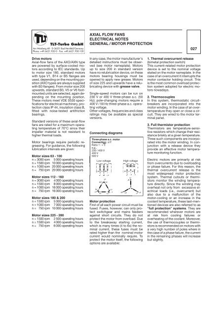
Connecting diagrams<br />
Three-phase a.c. motor<br />
Connection: �/Y<br />
Ratio 1 : � 3<br />
e.g.,<br />
230 / 400 V<br />
400 V<br />
500 V<br />
Low voltage High voltage<br />
Motor protection<br />
First of all each power circuit must be<br />
fused. Fuses, however, can only protect<br />
switchgear and mains feeders<br />
against short circuits. They do not<br />
protect the motor from overload. Due<br />
to the breakaway starting current,<br />
which is many times (4 to 6x) the nominal<br />
current, these fuses must be<br />
rated higher than the nominal motor<br />
current would nominally require. To<br />
protect the motor itself, the following<br />
options are available:<br />
027<br />
1. Thermal overcurrent release<br />
(bimetal protection switch)<br />
This current-related motor protection<br />
device is set to the nominal voltage<br />
stated on the motor nameplate. In the<br />
case of an overcurrent it interrupts the<br />
motor contactor holding circuit. This<br />
is the most common overload protection<br />
system adopted for electric motors<br />
nowadays.<br />
2. Thermocouples<br />
In this system, thermostatic circuitbreakers<br />
are incorporated into the<br />
motor winding. In the case of an overtemperature<br />
they open or close a circuit.<br />
They are wired to the motor terminal<br />
panel.<br />
3. Full thermistor protection<br />
Thermistors are temperature-sensitive<br />
resistors which change their resistance<br />
briskly at a given temperature.<br />
Three such components are incorporated<br />
into the motor winding. In conjunction<br />
with a release device they<br />
provide an effective motor temperature<br />
monitoring function.<br />
Electric motors are primarily at risk<br />
from overcurrents due to overloading<br />
or phase failure. For this reason, the<br />
thermal overcurrent release is the<br />
most widespread motor protection<br />
system. Thermal cutouts or thermistors<br />
monitor the winding temperature<br />
directly. Since the winding may<br />
overheat not only from excessive electrical<br />
loads (i.e., overcurrent) but<br />
also due to a malfunction of the<br />
motor-cooling or an increase in the<br />
coolant temperature, these last-mentioned<br />
devices are also referred to as<br />
"full protection" systems. They are<br />
recommended wherever motors are<br />
at risk from cooling failures or<br />
overheating of the coolant. Moreover,<br />
the use of thermocouples or thermistors<br />
is recommended on motors with<br />
a very high number of poles where in<br />
the case of a phase failure, the current<br />
in the remaining phases will increase<br />
but slightly.