Axial innen engl - TLT Turbo GmbH
Axial innen engl - TLT Turbo GmbH
Axial innen engl - TLT Turbo GmbH

You also want an ePaper? Increase the reach of your titles
YUMPU automatically turns print PDFs into web optimized ePapers that Google loves.
Am Weinberg 68 · D-36251 Bad Hersfeld/Germany<br />
Phone: +49.6621.950-0 · Fax: +49.6621.950-100<br />
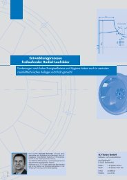
Important design notice:<br />
<strong>Axial</strong>-flow fans have a pronounced<br />
stall range starting on the left of the<br />
respective curve end. Due to the risk<br />
of fatigue failure, an axial-flow fan<br />
must not be operated in stall mode. It<br />
is therefore important when sizing<br />
these fans to allow for an appropriate<br />
safety margin around the stall point.<br />
The operating point should be located<br />
on the right-hand (steep) side of<br />
the curve. A pressure margin of approx.<br />
15% from the stall point is recommended.<br />
Stall<br />
margin<br />
Stall<br />
point<br />
Fan characteristic<br />
Operating point<br />
In selecting fans and their control systems,<br />
care should be taken to ensure<br />
that all operating points of the envisaged<br />
control range lie within the stable<br />
area of the fan characteristic.<br />
Flow direction<br />
Direct-driven fans are available with<br />
the airflow direction "D" (motor in<br />
outlet) or "S" (motor in inlet). The<br />
catalogue shows the characteristic<br />
curves for airflow direction "D" units.<br />
For "S" type fans, a correction of the<br />
fan characteristic must be applied as<br />
follows:<br />
Volume flow + 5 %<br />
Total pressure increase + 10 %<br />
In addition, 5% should be deducted<br />
from the efficiency value.<br />
Belt-driven fans are available with airflow<br />
direction "D" only.<br />
If - for whatever reason - a belt guard<br />
is to be provided inside the fan, an<br />
output reduction must be expected.<br />
The impellers are not designed for reversible<br />
or contra-rotating operation.<br />
AXIAL FLOW FANS<br />
WITH ADJUSTABLE BLADES AT REST<br />
SIZING INFORMATION<br />
Air inlet/outlet<br />
Our characteristic curves are based<br />
on the assumption that a uniformly<br />
swirl-free velocity distribution prevails<br />
at the fan inlet. It may therefore be necessary<br />
to install a bellmouth inlet in<br />
the case of free intake configurations,<br />
or to fit appropriate guide panels if the<br />
fan operates immediately downstream<br />
of a duct elbow.<br />
Antivibration mounts<br />
Size 224 – 900 fans operating at<br />
1000+ rpm and size 1000 – 2000 fans<br />
with speeds exceeding 750 rpm can<br />
be fitted on rubber antivibration<br />
mounts.<br />
Determining motor output<br />
We recommend that the calculated<br />
shaft horsepower (PW) should be increased<br />
by the following percentages:<br />
Direct-driven fans +5% to 10%<br />
Belt-driven fans +10% to 20%<br />
Motor terminal box for AXO types<br />
All fans of this type (sizes 315 – 1000)<br />
are supplied with an exterior terminal<br />
box fitted on the casing and wired to<br />
the motor terminal box.<br />
Motor terminal box for AXN types<br />
Fans up to size 1250 are supplied with<br />
an exterior terminal box fitted on the<br />
casing and wired to the motor terminal<br />
box.<br />
Important notes:<br />
Direct-driven fans are available<br />
only with the motor output ratings<br />
indicated in our price lists.<br />
(Please inquire for special motors).<br />
The max. motor outputs for beltdrive<br />
fans are stated on the characteristic<br />
curve sheets on page 139 –<br />
155.<br />
For maximum acceptable motor<br />
sizes please refer to the dimensional<br />
diagrams on pages 007 – 011.<br />
035<br />
Acoustics<br />
All acoustic performance data are<br />
given in the characteristic curve<br />
sheets and on the "Acoustic Data"<br />
pages. The information supplied is<br />
valid for the stated rotational speeds.<br />
Acoustic data for other rpm levels<br />
can be derived by approximation<br />
using the following formulas:<br />
For lower rpm:<br />
L 1 = L 2 – 45 [log ( n2 )]<br />
n1<br />
For higher rpm:<br />
L 2 = L 1 + 45 [log ( n2 )]<br />
n1<br />
To correct for a greater distance:<br />
Distance in m<br />
Decrease in sound pressure level (dB)<br />
The acoustic emissions of multiple<br />
axial-flow fans operating at the same<br />
sound volume can be determined<br />
using the following table:<br />
Number of units<br />
Increase in sound level (dB)<br />
If two not equally loud axial-flow fans<br />
are operated simultaneously, the following<br />
correction values should be<br />
added to the higher acoustic level:<br />
Level difference [dB]<br />
Value to be added [dB]<br />
Fans with two or more speeds<br />
In the characteristic curves appearing<br />
below, the effect of the<br />
Reynolds number has been taken<br />
into account. As a result, the known<br />
laws of proportionality are not applicable<br />
to all fan sizes, specifically at<br />
small diameters and low speeds.