Axial innen engl - TLT Turbo GmbH
Axial innen engl - TLT Turbo GmbH
Axial innen engl - TLT Turbo GmbH

You also want an ePaper? Increase the reach of your titles
YUMPU automatically turns print PDFs into web optimized ePapers that Google loves.
Am Weinberg 68 · D-36251 Bad Hersfeld/Germany<br />
Phone: +49.6621.950-0 · Fax: +49.6621.950-100<br />
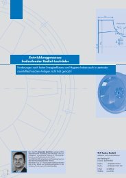
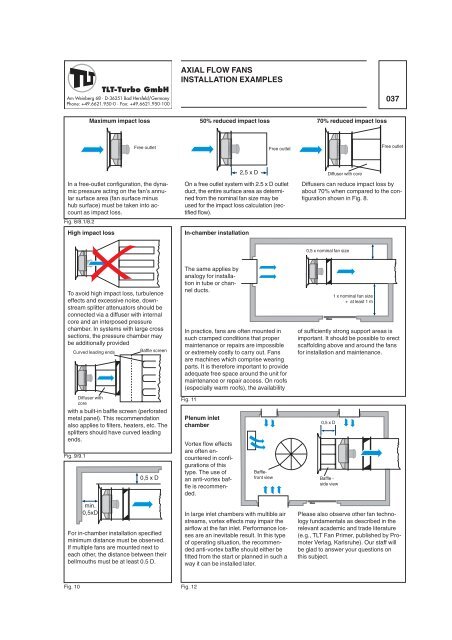
In a free-outlet configuration, the dynamic<br />
pressure acting on the fan’s annular<br />
surface area (fan surface minus<br />
hub surface) must be taken into account<br />
as impact loss.<br />
Fig. 8/8.1/8.2<br />
To avoid high impact loss, turbulence<br />
effects and excessive noise, downstream<br />
splitter attenuators should be<br />
connected via a diffuser with internal<br />
core and an interposed pressure<br />
chamber. In systems with large cross<br />
sections, the pressure chamber may<br />
be additionally provided<br />
Curved leading ends<br />
Baffle screen<br />
Diffuser with<br />
core<br />
with a built-in baffle screen (perforated<br />
metal panel). This recommendation<br />
also applies to filters, heaters, etc. The<br />
splitters should have curved leading<br />
ends.<br />
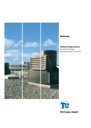
AXIAL FLOW FANS<br />
INSTALLATION EXAMPLES<br />
Maximum impact loss 50% reduced impact loss 70% reduced impact loss<br />
High impact loss<br />
Fig. 9/9.1<br />
min.<br />
0,5xD<br />
For in-chamber installation specified<br />
minimum distance must be observed.<br />
If multiple fans are mounted next to<br />
each other, the distance between their<br />
bellmouths must be at least 0.5 D.<br />
Free outlet Free outlet<br />
0,5 x D<br />
On a free outlet system with 2.5 x D outlet<br />
duct, the entire surface area as determined<br />
from the nominal fan size may be<br />
used for the impact loss calculation (rectified<br />
flow).<br />
In-chamber installation<br />
The same applies by<br />
analogy for installation<br />
in tube or channel<br />
ducts.<br />
In practice, fans are often mounted in<br />
such cramped conditions that proper<br />
maintenance or repairs are impossible<br />
or extremely costly to carry out. Fans<br />
are machines which comprise wearing<br />
parts. It is therefore important to provide<br />
adequate free space around the unit for<br />
maintenance or repair access. On roofs<br />
(especially warm roofs), the availability<br />
Fig. 11<br />
Fig. 10 Fig. 12<br />
Plenum inlet<br />
chamber<br />
Vortex flow effects<br />
are often encountered<br />
in configurations<br />
of this<br />
type. The use of<br />
an anti-vortex baffle<br />
is recommended.<br />
2,5 x D<br />
In large inlet chambers with multible air<br />
streams, vortex effects may impair the<br />
airflow at the fan inlet. Performance losses<br />
are an inevitable result. In this type<br />
of operating situation, the recommended<br />
anti-vortex baffle should either be<br />
fitted from the start or planned in such a<br />
way it can be installed later.<br />
Diffuser with core<br />
037<br />
Free outlet<br />
Diffusers can reduce impact loss by<br />
about 70% when compared to the configuration<br />
shown in Fig. 8.<br />
0,5 x nominal fan size<br />
Bafflefront<br />
view Baffle -<br />
side view<br />
1 x nominal fan size<br />
+ at least 1 m<br />
of sufficiently strong support areas is<br />
important. It should be possible to erect<br />
scaffolding above and around the fans<br />
for installation and maintenance.<br />
0,5 x D<br />
Please also observe other fan technology<br />
fundamentals as described in the<br />
relevant academic and trade literature<br />
(e.g., <strong>TLT</strong> Fan Primer, published by Promoter<br />
Verlag, Karlsruhe). Our staff will<br />
be glad to answer your questions on<br />
this subject.