Continental L-Head Overhaul Manual - Igor Chudov
Continental L-Head Overhaul Manual - Igor Chudov
Continental L-Head Overhaul Manual - Igor Chudov

Create successful ePaper yourself
Turn your PDF publications into a flip-book with our unique Google optimized e-Paper software.
Page 40 CONTINENTAL L-HEAD ENGINE MANUAL<br />
The range of a governor’s action is indicated<br />
by the differential between R.P.M. under<br />
load and that under no load.<br />
This can be rallied and the sensitivity of<br />
governor changed by changing the length<br />
of screw "n".<br />
To broaden the range of the governor and<br />
produce a more stable action, lengthen<br />
screw "E" and compensate for this change<br />
by turning.screw "B" in to restore<br />
Lengthening screw "E" changes<br />
speed.<br />
pull on<br />
spring to more nearly the arc of the lever<br />
action, thus having the effect of increasing<br />
~he spring rate.<br />
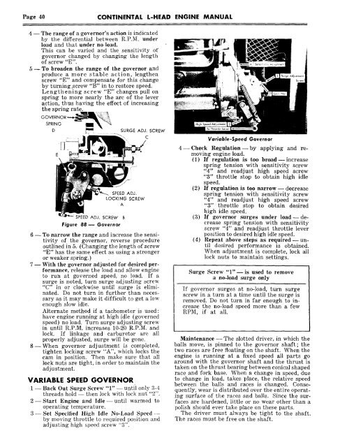
GOVERiX<br />
SPR~NG I~<br />
D ~ SURGE ADJ. SCREW<br />
C<br />
SPEED ADJ. SCREW B<br />
Figure 88-- Governor<br />
SPEED ADJ.<br />
LOCKING SCREW<br />
A<br />
6 -- To narrow the range and increase the sensitivity<br />
of the governor, reverse procedure<br />
outlined in 5. (Changing the length of screw<br />
"E" has the same effect as usinga stronger<br />
or weaker spring.)<br />
7 -- With the governor adjusted for desired performance,<br />
release the load and allow engine<br />
to run at governed speed, no load. If a<br />
surge is noted, turn surge adjusting screw<br />
"C" in or clockwise un.til surge is eliminated.<br />
Do not turn in ~urther than necessary<br />
as it may make it difficul.t to get a low<br />
enough slow idle.<br />
Alternate method if a tachometer is used:<br />
have engine running at high idle (governed<br />
speed) no load. Turn surge adjusting screw<br />
in until R.P.M. increases 10-20 R.P.M. and<br />
lock. If linkage and carburetor are all<br />
properly adjusted, surge will be gone.<br />
8--When governor adjustment is completed,<br />
tighten locking screw "A", which locks the<br />
cam in position. Then make sure that all<br />
lock nuts are tight, in order to maintain the<br />
adjustment.<br />
VARIABLE SPEED GOVERNOR<br />
1 -- Back Out Surge Screw "1" -- until only 3-4<br />
threads hold -- then lock with lock nut "2".<br />
2- Start Engine and Idle- until warmed to<br />
operating temperature.<br />
3--Set Specified High Idle No-Load Speedby<br />
moving throttle to required position and<br />
adjusting high speed screw "3".<br />
Variable-Speed Governor<br />
4- Check Regulation- by applying and removing<br />
engine load.<br />
(1) If regulation is too broad -- increase<br />
spring tension with sensitivity screw<br />
"4" and readjust high speed screw<br />
"3" throttle stop to obtain high idle<br />
speed.<br />
(2) If regulation is too narrow -- decrease<br />
spring tension with sensitivity screw<br />
"4" and readjust high speed screw<br />
"3" throttle stop to obtain desired<br />
high idle speed.<br />
(3) If governor surges under load--decrease<br />
spring tension with sensitivity<br />
screw "4" and readjust throttle lever<br />
position to desired high idle speed.<br />
(4) Repeat above steps as required--until<br />
desired performance is obtained.<br />
When adjustment is complete, lock all<br />
lock nuts to maintain settings.<br />
Surge Screw "1"--is used to remove<br />
a no-load surge only<br />
If governor surges at no-load, turn surge<br />
screw in a turn at a time until the surge is<br />
removed. Do not turn in far enough to increase<br />
the no-load speed more than a few<br />
RPM, if at all.<br />
Maintenance- The slotted driver, in which the<br />
balls move, is pinned to the governor shaft; the<br />
two races are free floating on the shaft. When the<br />
engine is running at a fixed speed all parts go<br />
around with the governor shaft and the thrust is<br />
taken on the thrust bearing between conical shaped<br />
race and fork base. When a change in speed, due<br />
to change in load, takes place, the relative speed<br />
between the balls and races is changed. Consequently,<br />
wear is distributed over the entire operating<br />
surface of the races and balls. Since the surfaces<br />
are hardened, little or no wear other than a<br />
polish should ever take place on these parts.<br />
The driver must always be tight to the shaft.<br />
The races must be free on the shaft.